High Torque Timing Pulleys S3M Type

Caution
- Please note that the swaged flange options, NFC, RFC, and LFC, are not reflected in the CAD data.
- Please check the content on our website as the PDF does not contain the most up-to-date information.
Product Description
[Material]
· Pulley: Aluminum alloy, S45C equivalent, SUS304
· Flange: Aluminum alloy, SPCC, SUS304
[Surface treatment]
· Clear anodize, black anodize, hard clear anodize (firm hardness 300HV~), electroless nickel plating, black iron oxide coating
Dimensional Drawing
■S3M
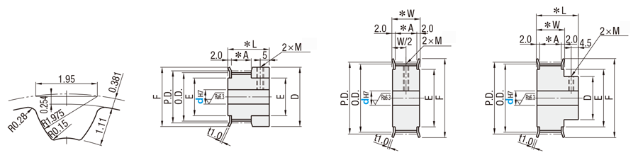
● Pulley Shape
Standard Tooth Profile
Shape K
[ ! ]
Shape A
[ ! ]
Shape B
| mm | Nominal | ||
| S3M060 | S3M100 | S3M150 | |
| A | 7 | 11 | 17 |
| W | 11 | 15 | 21 |
| L | 19 | 23 | 29 |
| dH7 Shaft Bore I.D. | M (Coarse) | Accessory Set Screws | Number of Accessories Included |
| 4 to 5 | M3 | M3 × 3 | 2 |
| 6 to 17 | M4 | M4 × 3 | |
| 18 to 33 | M5 | M5 × 4 | |
| 34 to 46 | M6 | M6 × 5 |
of the set screw.
| Dimension Range | Tolerance (㎜) | |
| Over | or Less | |
| 0.5 | 3 | ±0.1 |
| 3 | 6 | |
| 6 | 30 | ±0.2 |
| 30 | 120 | ±0.3 |
[ ! ] Shaft Bore Specs. H (Round hole), V or F (Stepped Hole), Y (Both Sides Stepped Hole) and WB (Two-stepped Hole) do not have tapped holes.
[ ! ] The tolerance of the tap position dimension from the boss end face and pulley end face is ±0.3.
[ ! ] Unless otherwise specified except for teeth and F dimensions, the dimension tolerance conforms to JIS B 0405 Class m.
[ ! ] Compatible with S3M type from Mitsuboshi Belting Ltd. as well as Bando Chemical Industries Ltd.
[ ! ] Surface treatment may not be applied to shaft bores.
[ ! ] No standard value is specified for chamfering of d dim.
H Round Hole
P Round Hole + Tap
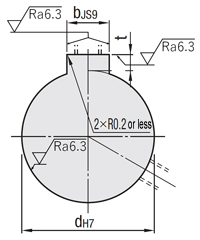
N New JIS Keyway + Tap
C Old JIS Keyway + Tap

[ ! ] For A-Shape pulley, the screw
holes are set at around 120° to
keep away from peaks.
[ ! ] Shaft Bore Specs. P is not
available for Shape A with 22 or
less teeth and nominal width
060.
[ ! ] Specify NK10 when selecting "New JIS Keywayed Bore" +
"Shaft Bore Diameter 10" + "Keyway Width 4.0 mm".
[ ! ] The difference between part number N10 and NK10 is the machining dimensions. See the table below, "New JIS Keyway Dimension Tolerance," for details.
[ ! ] The position of the keyway and the phase of the teeth are not guaranteed.
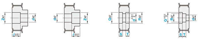
V Stepped Hole
F Stepped Hole (Counterbored Hole on the Hub Side)
Y Both Ends Stepped Hole
WB Two-stepped Hole
[NG] Not applicable
to Shape K
[ ! ] Z-V(d) ≥ 2
[ ! ] 2.0 ≤ J ≤ W-2.0
[ ! ] Applicable to
Shape B only
[ ! ] Z - F(d) ≥ 2
[ ! ] 2.0 ≤ J ≤ L-2.0
[ ! ] Applicable to
Shape A only
[ ! ] Q-Y(d) ≥ 2
[ ! ] R-Y(d) ≥ 2
[ ! ] S+T ≤ W-3.0
[ ! ] Shaft Bore Dia.
d is +0.1 / 0
[ ! ] S (T) ≥ 3.0
[ ! ] Applicable to
Shape A only
[ ! ] Q-R ≥ 2
[ ! ] R-WB(d) ≥ 2
[ ! ] S+T ≤ W-3.0
[ ! ] S (T) ≥ 3.0
| Nominal(N,C) | dH7 |
| 8 to 10(K) | +0.015 0 |
| 11 to 18 | +0.018 0 |
| 19 to 30 | +0.021 0 |
| 31 to 50 | +0.025 0 |
| Nominal(N) | bJS9 | t | ||
| 8 to 10 | 3 | ±0.0125 | 1.4 | +0.1 0 |
| 10K to 12 | 4 | ±0.0150 | 1.8 | |
| 13 to 17 | 5 | 2.3 | ||
| 18 to 22 | 6 | 2.8 | ||
| 23 to 30 | 8 | ±0.0180 | 3.3 | +0.2 0 |
| 31 to 38 | 10 | |||
| 39 to 44 | 12 | ±0.0215 | ||
| 45 to 50 | 14 | 3.8 | ||
| Nominal(C) | bJS9 | t | ||
| 10 to 12 | 4 | +0.022 +0.010 | 1.5 | +0.1 0 |
| 15 to 20 | 5 | 2 | ||
| Shape | Hole | ||||||
| H | P | N(C) | V | F | Y | WB | |
| A | ○ | ○ | ○ | ○ | ‐ | ○ | ○ |
| B | ○ | ○ | ○ | ○ | ○ | ‐ | ‐ |
| K | ○ | ○ | - | ‐ | ‐ | ‐ | ‐ |
| Type | Belt Width | [ M ] Material | [ S ] Surface Treatment | [ A ] Accessory Set Screws | |||
| 6 mm | 10 mm | 15 mm | Pulley | Flange | |||
| S3M060 | S3M100 | S3M150 | |||||
| HTPA | ● | ● | ● | Aluminum alloy | Aluminum alloy | Clear Anodize | SUS304 |
| HTPB | ● | ● | ● | Black Anodize | |||
| HTPK | ● | ● | ● | Hard Clear Anodize | |||
| HTPN | ● | ● | ● | Electroless nickel plating | |||
| HTPT | ● | ● | ● | S45C Equivalent | SPCC | - | SCM435 (Black Oxide) |
| HTPM | ● | ● | ● | Black Oxide Coating | |||
| HTPP | ● | ● | ● | Electroless nickel plating | |||
| HTPS | ● | ● | ● | SUS304 | SUS304 | - | SUS304 |
[ ! ] Due to vibrations during transportation, the set screw may become detached from the main body.
[ ! ] For orders with no flange, please specify the alteration NFC.