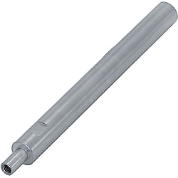
Rotary Shafts-One End Stepped and Tapped
Caution
Product Description
Expanded to a maximum length of 1000mm!
It is also possible to process key grooves, flats, and retaining rings on stepped parts with additional machining!
[Basic shape] Single step on one end
[Shaft end shape (left)] Stepped female thread
[Shaft end shape (right)] No processing
[Material] Equivalent to S45C, SUS304
[Additional machining available] Keyway, retaining ring groove, flat surface, slit cam groove, L dimension tolerance change, slotted groove, concentricity change, C chamfer width change, female thread depth change
Rotary Shafts – Stepped, Threaded Types
These rotary shafts have a single step with a female thread at one end, and a plain end at the other. Lengths up to 1000 mm are available, and keyways, flats and retaining ring grooves can be added to the stepped part. Materials: S45C equivalent, SUS304 and high-hardness stainless steel.
Dimensional drawing

Wrench-flat type
- Surface roughness of part D: h9 (cold-drawn bar) uses the first image below; h7 and g6 (ground bar) use the second image.


- High-hardness stainless steel may have a center hole.
Tolerance table
| D, P | h9 (cold-drawn bar) | h7 (ground bar) | g6 (ground bar) |
|---|---|---|---|
| 4–6 | 0 -0.030 | 0 -0.012 | -0.004 -0.012 |
| 8, 10 | 0 -0.036 | 0 -0.015 | -0.005 -0.014 |
| 12–18 | 0 -0.043 | 0 -0.018 | -0.006 -0.017 |
| 20–30 | 0 -0.052 | 0 -0.021 | -0.007 -0.020 |
| 35–50 | 0 -0.062 | 0 -0.025 | -0.009 -0.025 |
Roundness and straightness / Coaxiality and perpendicularity

D roundness
| D | Roundness M | |
|---|---|---|
| Over | Up to | |
| 5 | 13 | 0.004 |
| 13 | 20 | 0.005 |
| 20 | 40 | 0.006 |
| 40 | 50 | 0.007 |
L, F and SC dimensional tolerances
| Dimension | Dimension tolerance | |
|---|---|---|
| Over | Up to | |
| 2 | 6 | ±0.1 |
| 6 | 30 | ±0.2 |
| 30 | 120 | ±0.3 |
| 120 | 400 | ±0.5 |
| 400 | 1000 | ±0.8 |
- Conforms to JIS B 0405 m class (medium).
- For h9 (cold-drawn bar), D roundness, straightness, coaxiality and perpendicularity do not apply.
| Type | Tolerance | Material | Surface treatment | |||
|---|---|---|---|---|---|---|
| No. | Standard type | Wrench-flat type | D | P | ||
| ① | NSFRMHG | NSFRMHGS | h9 (cold-drawn bar) | h7 | S45C equivalent | - |
| SFRMHG | SFRMHGS | Black oxide | ||||
| PSFRMHG | PSFRMHGS | Electroless nickel plating | ||||
| SSFRMHG | SSFRMHGS | SUS304 | - | |||
| ② | NSFRMGG | NSFRMGGS | g6 | S45C equivalent | - | |
| SFRMGG | SFRMGGS | Black oxide | ||||
| PSFRMGG | PSFRMGGS | Electroless nickel plating | ||||
| SSFRMGG | SSFRMGGS | SUS304 | - | |||
| ③ | NSFRHG | NSFRHGS | h7 (ground bar) | h7 | S45C equivalent | - |
| SFRHG | SFRHGS | Black oxide | ||||
| PSFRHG | PSFRHGS | Electroless nickel plating | ||||
| SSFRHG | SSFRHGS | SUS304 | - | |||
| ④ | NSFRG | NSFRGS | g6 (ground bar) | g6 | S45C equivalent | - |
| SFRG | SFRGS | Black oxide | ||||
| PSFRG | PSFRGS | Electroless nickel plating | ||||
| SSFRG | SSFRGS | SUS304 | - | |||
| AHFRG | AHFRGS | High-hardness stainless steel Hardness 35HRC min. | - | |||
- Center hardness of high-hardness stainless steel is lower.
Part numbers and dimensions
Ordering example
| Item | Type | - | L | - | F | - | P | - | M | - | SC |
|---|---|---|---|---|---|---|---|---|---|---|---|
| ① D part h9 / P part h7 | SFRMHG30 | - | 250 | - | F30 | - | P16 | - | M10 | ||
| ③ h7 (ground bar), wrench-flat type | SFRHGS25 | - | 200 | - | F40 | - | P20 | - | M10 | - | SC30 |
| ④ g6 (ground bar) | SF-SSFRG20 | - | 200 | - | F20 | - | P18 | - | M12 |
① D part tolerance h9 (cold-drawn bar) / P part tolerance h7, ② D part tolerance h9 (cold-drawn bar) / P part tolerance g6 types
| Type | 0.1 mm increments | 1 mm increments | M (coarse) Selection | 1 mm increments | W | ℓ2 | (Y) max. | |||||||||||||
|---|---|---|---|---|---|---|---|---|---|---|---|---|---|---|---|---|---|---|---|---|
| Type | D | L | F | P | SC Wrench-flat type only | |||||||||||||||
| Standard type | Wrench-flat type | |||||||||||||||||||
| ① D part h9, P part h7 NSFRMHG SFRMHG PSFRMHG SSFRMHG (SSFRMHG: D13, 17, 18, 22 not available) ② D part h9, P part g6 NSFRMGG SFRMGG PSFRMGG SSFRMGG (SSFRMGG: D13, 17, 18, 22 not available) | ① D part h9, P part h7 NSFRMHGS SFRMHGS PSFRMHGS SSFRMHGS (SSFRMHGS: D13, 17, 18, 22 not available) ② D part h9, P part g6 NSFRMGGS SFRMGGS PSFRMGGS SSFRMGGS (SSFRMGGS: D13, 17, 18, 22 not available) | 6 | 15.0–498.0 | 2≤F≤P×5 | 5 | 2.6 | 3 | SC+ℓ2 ≤ L SC = 0 or SC ≥ 1 When SC ≤ M×3-F: W-M ≥ 2 | 5 | 8 | 500 | |||||||||
| 8 | 15.0–498.0 | For M3–M8: M+2 ≤ P < D For M10–M16: M+3 ≤ P < D For M20, M24: M+4 ≤ P < D | 2.6 | 3 | 4 | 5 | 7 | 500 | ||||||||||||
| 10 | 15.0–798.0 | 3 | 4 | 5 | 6 | 8 | 800 | |||||||||||||
| 12 | 15.0–898.0 | 3 | 4 | 5 | 6 | 8 | 10 | 10 | 900 | |||||||||||
| 13 | 15.0–898.0 | 3 | 4 | 5 | 6 | 8 | 11 | |||||||||||||
| 15 | 15.0–998.0 | 3 | 4 | 5 | 6 | 8 | 10 | 13 | 1000 | |||||||||||
| 16 | 15.0–998.0 | 4 | 5 | 6 | 8 | 10 | 12 | 14 | ||||||||||||
| 17 | 24.0–998.0 | 4 | 5 | 6 | 8 | 10 | 12 | |||||||||||||
| 18 | 24.0–998.0 | 4 | 5 | 6 | 8 | 10 | 12 | 15 | ||||||||||||
| 20 | 24.0–998.0 | 4 | 5 | 6 | 8 | 10 | 12 | 16 | 17 | |||||||||||
| 22 | 24.0–998.0 | 4 | 5 | 6 | 8 | 10 | 12 | 16 | 19 | |||||||||||
| 25 | 24.0–998.0 | 4 | 5 | 6 | 8 | 10 | 12 | 16 | 20 | 22 | ||||||||||
| 30 | 24.0–998.0 | 5 | 6 | 8 | 10 | 12 | 16 | 20 | 27 | 15 | ||||||||||
| 35 | 40.0–998.0 | 6 | 8 | 10 | 12 | 16 | 20 | 24 | 30 | |||||||||||
- L-SC≤N×3
③ h7 (ground bar) type
| Type | 0.1 mm increments | 1 mm increments | M (coarse) Selection | 1 mm increments | W | ℓ2 | (Y) max. | ||||||||||||||
|---|---|---|---|---|---|---|---|---|---|---|---|---|---|---|---|---|---|---|---|---|---|
| Type | D | L | F | P | SC Wrench-flat type only | ||||||||||||||||
| Standard type | Wrench-flat type | ||||||||||||||||||||
| NSFRHG SFRHG PSFRHG SSFRHG | NSFRHGS SFRHGS PSFRHGS SSFRHGS | 6 | 15.0–498.0 | 2≤F≤P×5 | 5 | 2.6 | 3 | SC+ℓ2 ≤ L SC = 0 or SC ≥ 1 When SC ≤ M×3-F: W-M ≥ 2 | 5 | 8 | 500 | ||||||||||
| 8 | 15.0–498.0 | For M3–M8: M+2 ≤ P < D For M10–M16: M+3 ≤ P < D For M20, M24: M+4 ≤ P < D For M30: M+5 ≤ P < D | 2.6 | 3 | 4 | 5 | 7 | 500 | |||||||||||||
| 10 | 15.0–798.0 | 3 | 4 | 5 | 6 | 8 | 800 | ||||||||||||||
| 12 | 15.0–898.0 | 3 | 4 | 5 | 6 | 8 | 10 | 10 | 900 | ||||||||||||
| 15 | 15.0–998.0 | 3 | 4 | 5 | 6 | 8 | 10 | 13 | 1000 | ||||||||||||
| 17 | 24.0–998.0 | 4 | 5 | 6 | 8 | 10 | 12 | 14 | |||||||||||||
| 20 | 24.0–998.0 | 4 | 5 | 6 | 8 | 10 | 12 | 16 | 17 | 1000 | |||||||||||
| 25 | 24.0–998.0 | 4 | 5 | 6 | 8 | 10 | 12 | 16 | 20 | 22 | |||||||||||
| 30 | 24.0–998.0 | 5 | 6 | 8 | 10 | 12 | 16 | 20 | 27 | 15 | |||||||||||
| 35 | 40.0–998.0 | 6 | 8 | 10 | 12 | 16 | 20 | 24 | 30 | ||||||||||||
| 40 | 40.0–998.0 | 10 | 12 | 16 | 20 | 24 | 30 | 36 | 20 | ||||||||||||
| 50 | 40.0–998.0 | 12 | 16 | 20 | 24 | 30 | 41 | ||||||||||||||
- L-SC≤N×3
④ g6 (ground bar) type
| Type | 0.1 mm increments | 1 mm increments | M (coarse) Selection | 1 mm increments | W | ℓ2 | (Y) max. | ||||||||||||||
|---|---|---|---|---|---|---|---|---|---|---|---|---|---|---|---|---|---|---|---|---|---|
| Type | D | L | F | P | SC Wrench-flat type only | ||||||||||||||||
| Standard type | Wrench-flat type | ||||||||||||||||||||
| NSFRG SFRG PSFRG SSFRG AHFRG (sizes marked * only) | NSFRGS SFRGS PSFRGS SSFRGS AHFRGS (sizes marked * only) | * 6 | 15.0–498.0 | 2 ≤ F ≤ P×5 AHFRG and AHFRGS only: 2 ≤ F ≤ P×4 | 5 | 2.6 | 3 | SC+ℓ2 ≤ L SC = 0 or SC ≥ 1 When SC ≤ M×3-F: W-M ≥ 2 | 5 | 8 | 500 | ||||||||||
| * 8 | 15.0–498.0 | For M3–M8: M+2 ≤ P < D For M10–M16: M+3 ≤ P < D For M20, M24: M+4 ≤ P < D For M30: M+5 ≤ P < D | 2.6 | 3 | 4 | 5 | 7 | 500 | |||||||||||||
| *10 | 15.0–798.0 | 3 | 4 | 5 | 6 | 8 | 800 | ||||||||||||||
| *12 | 15.0–898.0 | 3 | 4 | 5 | 6 | 8 | 10 | 10 | 900 | ||||||||||||
| 13 | 15.0–898.0 | 3 | 4 | 5 | 6 | 8 | 11 | ||||||||||||||
| *15 | 15.0–998.0 | 3 | 4 | 5 | 6 | 8 | 10 | 13 | 1000 | ||||||||||||
| *16 | 15.0–998.0 | 4 | 5 | 6 | 8 | 10 | 12 | 14 | |||||||||||||
| 17 | 24.0–998.0 | 4 | 5 | 6 | 8 | 10 | 12 | ||||||||||||||
| 18 | 24.0–998.0 | 4 | 5 | 6 | 8 | 10 | 12 | 15 | |||||||||||||
| *20 | 24.0–998.0 | 4 | 5 | 6 | 8 | 10 | 12 | 16 | 17 | 1000 | |||||||||||
| 22 | 24.0–998.0 | 4 | 5 | 6 | 8 | 10 | 12 | 16 | 19 | ||||||||||||
| *25 | 24.0–998.0 | 4 | 5 | 6 | 8 | 10 | 12 | 16 | 20 | 22 | |||||||||||
| 30 | 24.0–998.0 | 5 | 6 | 8 | 10 | 12 | 16 | 20 | 27 | 15 | |||||||||||
| 35 | 40.0–998.0 | 6 | 8 | 10 | 12 | 16 | 20 | 24 | 30 | ||||||||||||
| 40 | 40.0–998.0 | 10 | 12 | 16 | 20 | 24 | 30 | 36 | 20 | ||||||||||||
| 50 | 40.0–998.0 | 12 | 16 | 20 | 24 | 30 | 41 | ||||||||||||||
- When D-P ≤ 2, step chamfer C is 0.2 or less.
- L-SC ≤ N×3
- For AHFRG and AHFRGS, D10–25, overall length (Y) is max. 800.
Alterations
Alterations are available. Refer to the alteration table for applicable codes, dimensional limits and conditions.
For details, please see the PDF catalog.
Technical reference
Keyway dimensions
| Shaft dia. | b | t | r | ||
|---|---|---|---|---|---|
| Basic size | Tolerance (N9) | Basic size | Tolerance | ||
| 6–7 | 2 | -0.004 -0.029 | 1.2 | +0.1 0 | 0.08–0.16 |
| 8–10 | 3 | 1.8 | |||
| 11–12 | 4 | 0 -0.03 | 2.5 | ||
| 13–17 | 5 | 3.0 | 0.16–0.25 | ||
| 18–22 | 6 | 3.5 | |||
| 23–30 | 8 | 0 -0.036 | 4.0 | +0.2 0 | |
| 31–38 | 10 | 5.0 | 0.25–0.4 | ||
| 39–44 | 12 | 0 -0.043 | 5.0 | ||
| 45–50 | 14 | 5.5 | |||
- b ≤ A, E, C ≤ 100
- Not available for D = 2–5.
Rotary shaft retaining ring groove dimensions by shaft diameter
| Shaft dia. | d tolerance | Groove width (m) tolerance | Applicable retaining ring | Material | ||
|---|---|---|---|---|---|---|
| 2 | 1.2 | +0.06 0 | 0.4 | +0.05 0 | JIS type E 1.2 | SUS304 |
| 2.5 | 1.5 | 0.5 | JIS type E 1.5 | |||
| 3 | 2 | JIS type E 2 | ||||
| 4 | 3 | 0.7 | +0.1 0 | JIS type E 3 | ||
| 5 | 4 | +0.075 0 | JIS type E 4 | |||
| 6 | 5 | JIS type E 5 | ||||
| 7 | 6 | 0.9 | JIS type E 6 | |||
| 8 | 7 | +0.09 0 | JIS type E 7 | |||
| 9 | 8 | JIS type E 8 | ||||
| 10 | 9.6 | 0/-0.09 | 1.15 | +0.14 0 | JIS type C 10 | SUS304 |
| 11 | 10.5 | 0 -0.11 | JIS type C 11 | |||
| 12 | 11.5 | JIS type C 12 | ||||
| 13 | 12.4 | JIS type C 13 | ||||
| 14 | 13.4 | JIS type C 14 | ||||
| 15 | 14.3 | JIS type C 15 | ||||
| 16 | 15.2 | JIS type C 16 | ||||
| 17 | 16.2 | JIS type C 17 | ||||
| 18 | 17 | 1.35 | JIS type C 18 | |||
| 19 | 18 | JIS type C 19 | ||||
| Shaft dia. | d tolerance | Groove width (m) tolerance | Applicable retaining ring | Material | ||
|---|---|---|---|---|---|---|
| 20 | 19 | 0 -0.21 | 1.35 | +0.14 0 | JIS type C 20 | SUS304 |
| 21 | 20 | JIS type C 21 | ||||
| 22 | 21 | JIS type C 22 | ||||
| 23 | 22 | JIS type C 23 | ||||
| 24 | 22.9 | JIS type C 24 | ||||
| 25 | 23.9 | JIS type C 25 | ||||
| 26 | 24.9 | JIS type C 26 | ||||
| 28 | 26.6 | 1.65 | JIS type C 28 | |||
| 29 | 27.6 | JIS type C 29 | ||||
| 30 | 28.6 | JIS type C 30 | ||||
| 32 | 30.3 | 0 -0.25 | JIS type C 32 | |||
| 35 | 33 | JIS type C 35 | ||||
| 40 | 38 | 1.9 | JIS type C 40 | |||
| 45 | 42.5 | JIS type C 45 | ||||
| 50 | 47 | 2.2 | JIS type C 50 | |||
- Groove width (m) follows the former JIS standard JIS B 2805 (1978).
(Reference) center hardness of high-hardness stainless steel
| D | Center hardness (HRC) |
|---|---|
| 3 | 35 or more |
| 4 | 35 or more |
| 5 | 35 or more |
| 6 | 35 or more |
| 8 | 35 or more |
| 10 | 30 or more |
| 12 | 30 or more |
| 15 | 30 or more |
| 16 | 30 or more |
| 20 | 25 or more |
| 25 | 25 or more |
(Reference) mechanical properties
| Material | Tensile strength (MPa) | Yield point (0.2% proof stress) (MPa) | Young's modulus (GPa) | Shear modulus (GPa) | Poisson's ratio |
|---|---|---|---|---|---|
| S45C | 570 or more | 345 or more | 200 or more | 77 or more | 0.3 |
| SUS304 | 520 or more | 210 or more | 193 or more | 74 or more | 0.3 |
| SCM435 | 930 or more | 785 or more | 206 or more | 79 or more | 0.3 |
| High-hardness stainless steel | 1102 | 715 | 199 | 77 | 0.3 |
Chemical composition (%)
| C | Si | Mn | P | S | Ni | Cr |
| 0.15-0.25 | ≤0.50 | 7.5-9.5 | ≤0.05 | ≥0.12 | 1.5-3.0 | 13-15 |
[O-ring details]
| O-ring material | Hardness | Color | Type |
|---|---|---|---|
| Urethane rubber | 94 | Milky white | Iron Rubber O-ring P series (NOK) |
| Nitrile rubber | 70 | Black | JIS B 2401 P series (NOK) |
| Nitrile rubber | 90 | Black | |
| Fluororubber | 70 | Black |
Application examples
