Rotary Shafts - End Shape Selectable
Caution
Product Description
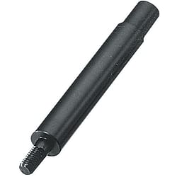
[Features]Shaft end shapes can be freely combined. The basic shape can be selected from straight, 1 step on 1 end, and 1 step on both ends.
Rotary shafts: end shape selectable
Shaft end shapes can be combined freely for each end. The basic shape can be straight, single step on one end, or single step on both ends. Choose the left and right end shapes (A to J), then the dimensions that apply. If only one end needs machining, select shape A for the other end.
Dimensional drawing
Blank shape (shape A at both ends)

- To machine only one shaft end, select shape A for the other end.
- Dimension (Y) must satisfy (Y) ≤ D×50.
- If dimension L is no more than the pilot hole depth of the female thread, the pilot hole may go through.
- H and J machining is not symmetrical.
- No retaining rings are supplied for F and G machining.
Tolerances for unspecified dimensions
| Size range | Tolerance (mm) | |
|---|---|---|
| Over | Up to | |
| 0.5 | 3 | ±0.1 |
| 3 | 6 | ±0.1 |
| 6 | 30 | ±0.2 |
| 30 | 120 | ±0.3 |
| 120 | 400 | ±0.5 |
| 400 | 1000 | ±0.8 |
- Conforms to JIS B 0405 m class (medium).
| Type | Material | Surface treatment |
|---|---|---|
| NSFR□□ | S45C equivalent | - |
| SFR□□ | Black oxide | |
| PSFR□□ | Electroless nickel plating | |
| SSFR□□ | SUS304 | - |
| Left shaft end shape | Right shaft end shape | Machining conditions |
|---|---|---|
| A | A | - |
| B | B | M3–8: M ≤ D-2 M10–16: M ≤ D-3 M20, 24: M ≤ D-4 M30: M ≤ D-5 |
| C | C | P(Q) = M(N) Specify the M(N) dimension. P(Q) does not need to be specified. |
| D | D | - |
| E | E | M3–8: M(N) ≤ P(Q)-2 M10–16: M(N) ≤ P(Q)-3 M20, 24: M(N) ≤ P(Q)-4 M30: M(N) ≤ P(Q)-5 |
| F | F | D = 27, 31, 33, 34, 36, 37, 38, 39, 41, 42, 43, 44, 46, 47, 48 and 49 cannot be specified |
| G | G | P and Q = 27, 31, 33, 34, 36, 37, 38, 39, 41, 42, 43, 44, 46, 47, 48 and 49 cannot be specified |
| H | H | Hex socket dimensions apply to D ≤ 30 |
| J | J | R(W)-M(N)≥t D-R-M≥2 D-W-N ≥ 2 (tap depth) M×2 N×2 (see table below) |
R(W)-M(N)≥t
| M(N) | tmin |
| 4–5 | 0.8 |
| 6–12 | 1.0 |
Part numbers and dimensions
Ordering example
| Type | - | D | - | L | - | F | - | B | - | M | - | T | - | Q | - | N |
|---|---|---|---|---|---|---|---|---|---|---|---|---|---|---|---|---|
| SFRCE | - | D15 | - | L350 | - | F20 | - | B16 | - | M8 | - | T20 | - | Q14 | - | N6 |
| Type | 1 mm increments | 0.1 mm increments | 1 mm increments | Selection | 1 mm increments | C | |||||||
|---|---|---|---|---|---|---|---|---|---|---|---|---|---|
| Type | Left shaft end shape | Right shaft end shape | D | L | F, T | B, S | H, U | P, Q | M, N | R, W | |||
| NSFR SFR PSFR SSFR | A B C D E F G H J | A B C D E F G H J | 6–50 | 20.0–800.0 (L≤D×50) | 2≤F≤P×5 2≤T≤Q×5 | When M, N ≤ 10: 2 ≤ B ≤ M×3 2 ≤ S ≤ N×3 and B ≤ F-3 S ≤ T-3 When M, N ≥ 12: 2 ≤ B ≤ M×3 2 ≤ S ≤ N×3 and B ≤ F-5 S ≤ T-5 B ≥ Pitch×3 S ≥ Pitch×3 | When D, P, Q ≤ 6: 2 ≤ H, U When 6 < D, P, Q ≤ 10: 3 ≤ H, U When 10 < D, P, Q ≤ 20: 4 ≤ H, U When 20 < D, P, Q: 5 ≤ H, U | D/3 ≤ P, Q < D | D≥M+4+R D≥N+4+W R≥M+3 W≥N+3 | 0.5 | |||
| 3 | 4 | 5 | |||||||||||
| 6 | 8 | 10 | |||||||||||
| 12 | 16 | 20 | |||||||||||
| 24 | 30 | ||||||||||||
- D31, 37, 39, 41–44 and 46–49 cannot be selected.
| Coarse thread pitch | |
|---|---|
| M・N (P・Q) | pitch |
| 3 | 0.5 |
| 4 | 0.7 |
| 5 | 0.8 |
| 6 | 1.0 |
| 8 | 1.25 |
| 10 | 1.5 |
| 12 | 1.75 |
| 16 | 2.0 |
| 20 | 2.5 |
| 24 | 3.0 |
| 30 | 3.5 |
| Fine thread pitch | |
|---|---|
| M・N (PMC・QMC) | pitch |
| 3 | 0.35 |
| 4 | 0.5 |
| 5 | |
| 6 | 0.75 |
| 8 | 1.0 |
| 10 | |
| 12 | |
| 15 | |
| 17 | |
| 20 | |
| 25 | 1.5 |
| 30 | |
| 35 | |
| 40 | |
Alterations
Alterations are available. Refer to the alteration table for applicable codes, dimensional limits and conditions.
For details, please see the PDF catalog.
Technical reference
Rotary shaft retaining ring groove dimensions by shaft diameter
| Shaft dia. | d tolerance | Groove width (m) tolerance | Applicable retaining ring | Material | ||
|---|---|---|---|---|---|---|
| 2 | 1.2 | +0.06 0 | 0.4 | +0.05 0 | JIS type E 1.2 | SUS304 |
| 2.5 | 1.5 | 0.5 | JIS type E 1.5 | |||
| 3 | 2 | JIS type E 2 | ||||
| 4 | 3 | 0.7 | +0.1 0 | JIS type E 3 | ||
| 5 | 4 | +0.075 0 | JIS type E 4 | |||
| 6 | 5 | JIS type E 5 | ||||
| 7 | 6 | 0.9 | JIS type E 6 | |||
| 8 | 7 | +0.09 0 | JIS type E 7 | |||
| 9 | 8 | JIS type E 8 | ||||
| 10 | 9.6 | 0/-0.09 | 1.15 | +0.14 0 | JIS type C 10 | SUS304 |
| 11 | 10.5 | 0 -0.11 | JIS type C 11 | |||
| 12 | 11.5 | JIS type C 12 | ||||
| 13 | 12.4 | JIS type C 13 | ||||
| 14 | 13.4 | JIS type C 14 | ||||
| 15 | 14.3 | JIS type C 15 | ||||
| 16 | 15.2 | JIS type C 16 | ||||
| 17 | 16.2 | JIS type C 17 | ||||
| 18 | 17 | 1.35 | JIS type C 18 | |||
| 19 | 18 | JIS type C 19 | ||||
| Shaft dia. | d tolerance | Groove width (m) tolerance | Applicable retaining ring | Material | ||
|---|---|---|---|---|---|---|
| 20 | 19 | 0 -0.21 | 1.35 | +0.14 0 | JIS type C 20 | SUS304 |
| 21 | 20 | JIS type C 21 | ||||
| 22 | 21 | JIS type C 22 | ||||
| 23 | 22 | JIS type C 23 | ||||
| 24 | 22.9 | JIS type C 24 | ||||
| 25 | 23.9 | JIS type C 25 | ||||
| 26 | 24.9 | JIS type C 26 | ||||
| 28 | 26.6 | 1.65 | JIS type C 28 | |||
| 29 | 27.6 | JIS type C 29 | ||||
| 30 | 28.6 | JIS type C 30 | ||||
| 32 | 30.3 | 0 -0.25 | JIS type C 32 | |||
| 35 | 33 | JIS type C 35 | ||||
| 40 | 38 | 1.9 | JIS type C 40 | |||
| 45 | 42.5 | JIS type C 45 | ||||
| 50 | 47 | 2.2 | JIS type C 50 | |||
About high-hardness stainless steel: an original MISUMI material that combines high hardness, high strength and corrosion resistance. It does not correspond to any JIS SUS grade (such as SUS304 or SUS440C).
Differences from linear shafts (basic specifications)
| D | Roundness M | |||
|---|---|---|---|---|
| Over | Up to | Rotary shaft (g6, h7, not hardened) | Shaft (g6, h5, hardened) | Shaft (f8, not hardened) |
| 2 | 2.5 | 0.006 | 0.004 | - |
| 3 | 13 | 0.004 | 0.004 | D5-9, 0.011 |
| 13 | 20 | 0.005 | 0.005 | D10-17, 0.014 |
| 20 | 40 | 0.006 | 0.006 | D18-29, 0.017 |
| 40 | 50 | 0.007 | 0.007 | D30-49, 0.020 |
| Straightness K | ||||
| D | L | Rotary shaft (g6, h7, not hardened) | Shaft (g6, h5, hardened) | Shaft (f8, not hardened) |
|---|---|---|---|---|
| 2, 2.5 | No condition | 0.1 | - | - |
| 3, 4 | No condition | 0.03 | (L/100)×0.05 or less | - |
| 5 | No condition | 0.02 | (L/100)×0.03 or less | - |
| 6–50 | 100 or less | 0.01 | 0.01 or less | No D condition: 0.025 or less |
| Over 100 | (L/100)×0.01 or less | No D condition (L/100)×0.025 or less | ||
| Coaxiality (male thread / stepped types) | |
| Rotary shaft (g6, h7, not hardened) | Shaft (g6, h5, hardened) |
|---|---|
| 0.06 | 0.1 |
| Perpendicularity | |
| Rotary shaft (g6, h7, not hardened) | Shaft (g6, h5, hardened) |
|---|---|
| 0.05 | 0.2 |
[O-ring details]
| O-ring material | Hardness | Color | Type |
|---|---|---|---|
| Urethane rubber | 94 | Milky white | Iron Rubber O-ring P series (NOK) |
| Nitrile rubber | 70 | Black | JIS B 2401 P series (NOK) |
| Nitrile rubber | 90 | Black | |
| Fluororubber | 70 | Black |