Single Axis Units Rolled Ball Screw With Cover

Brand :
MISUMI
Caution
Product Description
Product Overview of Belt Actuators/Drives and Accessories
Belt Actuators/Drives and Accessories E-KUA/E-KUAC single axis unit, which has standardized
the mechanism self-made by the customer with high usage frequency, is driven by rolled/precision ball screw to achieve high precision positioning. High-load transfer is also made possible by using a linear guide for medium and heavy load.
Belt Actuators/Drives and Accessories, A single axis unit with cover can prevent damage to the single axis unit caused by dropping small parts, etc., and prevent liquids
such as adhesive or grease from dripping inside the single axis unit. Safe use is ensured, significantly reducing magement costs.
the mechanism self-made by the customer with high usage frequency, is driven by rolled/precision ball screw to achieve high precision positioning. High-load transfer is also made possible by using a linear guide for medium and heavy load.
Belt Actuators/Drives and Accessories, A single axis unit with cover can prevent damage to the single axis unit caused by dropping small parts, etc., and prevent liquids
such as adhesive or grease from dripping inside the single axis unit. Safe use is ensured, significantly reducing magement costs.
Product Features of Belt Actuators/Drives and Accessories
Feature 1 : Belt Actuators/Drives and Accessories high precision. Achieves high precision positioning through the combination of linear guide and ball screw.
Feature 2 : Belt Actuators/Drives and Accessories low cost. Saves time in design, procurement and assembly. Significantly reduces labor costs for customers.
Feature 3 : Belt Actuators/Drives and Accessories heavy load resistance. Suitable for high and heavy load transfer thanks to the use of a linear guide for medium and heavy load.
Feature 2 : Belt Actuators/Drives and Accessories low cost. Saves time in design, procurement and assembly. Significantly reduces labor costs for customers.
Feature 3 : Belt Actuators/Drives and Accessories heavy load resistance. Suitable for high and heavy load transfer thanks to the use of a linear guide for medium and heavy load.
Structure Features of Belt Actuators/Drives and Accessories
Belt Actuators/Drives and Accessories, Adopts a lightweight aluminum base with high rigidity, featuring a ball linear guide.
Driven by rolled screw, two products (without cover type and with cover type) are added to the lineup.
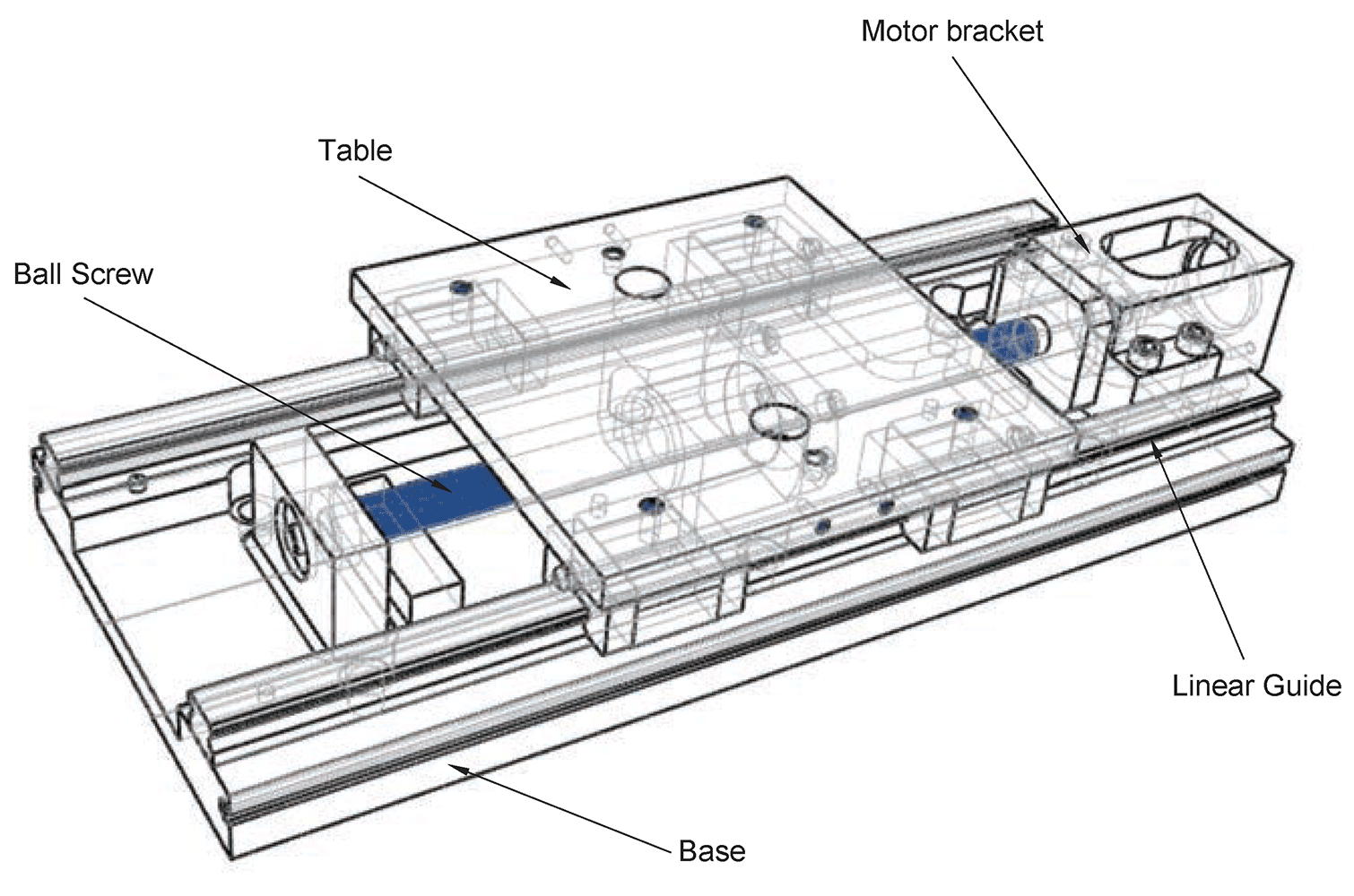
Driven by rolled screw, two products (without cover type and with cover type) are added to the lineup.
Dimensional Drawing of Belt Actuators/Drives and Accessories
 Accessories Accessories |  Material Material |  Surface Treatment Surface Treatment | Quantity | Note |
| Hexagon socket head bolt M5×10 | Iron | Trivalent Chromate Treatment (Black) | 4 | For fixing bracket |
| Part | Base | Table | Motor Bracket | Nut Bracket | Fixed Side Screw Support Unit | Support Side Bearing Housing | Stopper |
| Material | Aluminum Alloy | Aluminum Alloy | Aluminum Alloy | Aluminum Alloy | Iron | Aluminum Alloy | Resin |
| Surface Treatment | Black Anodized | Black Anodized | Black Anodized | Black Anodized | Ferroferric Oxide Protective Film | Black Anodized | - |

Specification Table of Belt Actuators/Drives and Accessories

| Part Number | Selection | Rolled Ball Screw | W Workbench Width | H Total Height | H1 Guide Height | H2 Axis Height | Table | |||||||
 Type Type |  No. No. |  L LBase Length |  L1 L1Table Length | Diameter | Lead | W | t2 | M1 | P1 | P2 | ||||
| E-KUAC | 1510L 1520L | 340 | 150 | 15 | 10 20 | 220 | 74 | 28 | 32 | 220 | 22 | M5 | 120 | 195 |
| 400 | ||||||||||||||
| 460 | ||||||||||||||
| 520 | ||||||||||||||
| 580 | ||||||||||||||
| 2010L 2020L | 20 | 89 | 39 | 40 | ||||||||||
| 640 | ||||||||||||||
| 700 | ||||||||||||||
| 78 | 28 | 34 | ||||||||||||
| 760 | ||||||||||||||
| 820 | ||||||||||||||
| Part Number | Base | Base Mounting Hole | Motor Mounting Related Dimensions | |||||||||||||||||||||||||||||||||||||||||||||||||||||||||
| Type | No. | W1 | H4 | t1 | h1 | P3 | h | Q | S | P.C.D | D | D1 | H3 | N | N1 | N2 | N3 | d | M2 | R | ||||||||||||||||||||||||||||||||||||||||
| E-KUAC | 1510L 1520L | 208 | 49 | 12 | 20 | 120 | 11.5 |
|
| 70 | 50 | 45 | 62 | 45 | 5 | 40 | 15 | 10 | M5 | 10 | ||||||||||||||||||||||||||||||||||||||||
| 2010L | 61 | 29 | 70 | 57.5 | 39.5 | 20 | 12 | |||||||||||||||||||||||||||||||||||||||||||||||||||||
| 2020L | 55 | 20 | 64 | |||||||||||||||||||||||||||||||||||||||||||||||||||||||||
*L=340 is suitable for 1510L only, and L=400 is suitable for 1510L and 2010L only.
■ Applicable Servo Motor Table
■ Precision·Allowable Static Load
■ Applicable Servo Motor Table
| Manufacturers | Part Number | Output Power (W) | Square Flange |
| Yaskawa Electric | SGM7J-02 | 200 | □60 |
| SGM7J-04 | 400 | ||
| Mitsubishi Electric | HG-MR23 | 200 | |
| HG-KR23 | 200 | ||
| HF-MP23 | 200 | ||
| HF-KP23 | 200 | ||
| HG-MR43 | 400 | ||
| HG-KR43 | 400 | ||
| HF-MP43 | 400 | ||
| HF-KP43 | 400 |
■ Precision·Allowable Static Load
| Part Number | *Positioning Repeatability (mm) | Allowable Static Load (kg) | *Parallelism (mm) | ||||||||||||||||||||||
| Type | No. | Horizontal | Vertical | ||||||||||||||||||||||
| Rolled Ball Screw E-KUAC | 1510L | ±0.05 | 2897 | 153 |
| ||||||||||||||||||||
| 1520L | |||||||||||||||||||||||||
| 2010L | 4345 | 169 | |||||||||||||||||||||||
| 2020L | |||||||||||||||||||||||||

■ Ball Screw Coupling Side Shaft End Alterations
| Alterations | Code | Spec. | |||||||
| Machining fixed side shaft end keyways | KC | Adds keyways. KC= 1mm increments Ordering Code KC10 |
| ||||||
 | |||||||||
| Machining fixed side shaft end keyways | KLC | The machining position of keyways can be specified. K, S= 1mm increments Ordering Code KLC-K5-S2 |
| ||||||
 | |||||||||
| Machining fixed side shaft end plane | SC | Adds planes. SC= 1mm increments Ordering Code SC7 |
| ||||||
 | |||||||||
| Machining a plane at fixed side shaft end (2 places) | SWC | Adds planes at 2 places (90° position). SWC= 1mm increments Ordering Code SWC7 |
| ||||||
 | |||||||||
■ Single Axis Actuators Cover Specification Optical Sensor
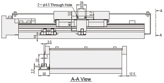
■ Cover Specification Optical Sensor Dimensions Table
| Applicable Part Number | Code |
| E-KUAC 1510L/1520L | CW1 CW2 CW3 |
| E-KUAC 2010L/2020L |
Example Use of Belt Actuators/Drives and Accessories

(1) Deburring Equipment Unit
Model : E-KUAC1505-340-150
Description : Movement of deburring brush. Especially suitable for working conditions with variable lifting speed and durability requirements.
Application : A sufficiently rigid device is required to prevent vibration.
Model : E-KUAC1505-340-150
Description : Movement of deburring brush. Especially suitable for working conditions with variable lifting speed and durability requirements.
Application : A sufficiently rigid device is required to prevent vibration.

(2) Movable Grinding Head Unit
Model : E-KUHC2010L-400-200
Description : Movement and positioning for bending and grinding equipment of crankshafts.
Application : The part of the device that deviates from the base plate.
Model : E-KUHC2010L-400-200
Description : Movement and positioning for bending and grinding equipment of crankshafts.
Application : The part of the device that deviates from the base plate.

(3) Welding Head Unit
Model: E-KUAC2010L-580-200
Description: Movement and positioning of the sliding part during equidistant welding operations of section steel spot welding machines.
Application: A sufficiently rigid device is required to prevent clamping.
Model: E-KUAC2010L-580-200
Description: Movement and positioning of the sliding part during equidistant welding operations of section steel spot welding machines.
Application: A sufficiently rigid device is required to prevent clamping.
Application Industries of Belt Actuators/Drives and Accessories


Usage Method of Belt Actuators/Drives and Accessories
■ Mounting Method of Belt Actuators/Drives and Accessories
Mount by positioning on the side of the base.
 To ensure the precision of the single axis unit, fix it to an iron plate with flatness of ±0.02mm or less and
thickness of 20mm or more through the mounting holes of the base, otherwise the base will be deformed and jamming will occur.
(1) Accessory Installation Diagram of Belt Actuators/Drives and Accessories
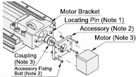
(2) Cover Installation Procedure of Belt Actuators/Drives and Accessories
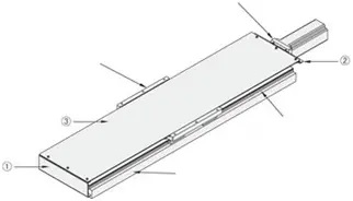
Step 1 : Fix the KU□C body on the device or workbench used by the customer.
Step 2 : Install the attached brackets ①② onto the body.
Step 3 : Fix the attached cover ③ onto the attached brackets ①② already installed in Step 2.
■ Belt Actuators/Drives and Accessories Maintenance Method
(1) Grease Replenishment Method
After applying grease directly to the ball screw, slide the workbench over the full stroke to achieve overall uniform application.
Insert the grease gun into the nozzle on the linear guide and inject grease.
After injection, move the table over the full stroke several times to achieve overall uniform application.
Grease: Showa Shell Albania Grease S2.
(2) Frequency of Grease Replenishment
Replenish grease every 6 months (or when the travel distance reaches 1000KM).
The replenishment interval varies with operating conditions and operating environment. Please make appropriate judgments.
Mount by positioning on the side of the base.
 To ensure the precision of the single axis unit, fix it to an iron plate with flatness of ±0.02mm or less and
thickness of 20mm or more through the mounting holes of the base, otherwise the base will be deformed and jamming will occur.
(1) Accessory Installation Diagram of Belt Actuators/Drives and Accessories
Note 1. Dowel pin is pressed into the motor bracket.
Note 2. Accessory and 4 M3x10 fixing bolts are included.
Note 3. Motor and coupling are not included.
Note 2. Accessory and 4 M3x10 fixing bolts are included.
Note 3. Motor and coupling are not included.
(2) Cover Installation Procedure of Belt Actuators/Drives and Accessories
Step 1 : Fix the KU□C body on the device or workbench used by the customer.
Step 2 : Install the attached brackets ①② onto the body.
Step 3 : Fix the attached cover ③ onto the attached brackets ①② already installed in Step 2.
■ Belt Actuators/Drives and Accessories Maintenance Method
(1) Grease Replenishment Method
After applying grease directly to the ball screw, slide the workbench over the full stroke to achieve overall uniform application.
Insert the grease gun into the nozzle on the linear guide and inject grease.
After injection, move the table over the full stroke several times to achieve overall uniform application.
Grease: Showa Shell Albania Grease S2.(2) Frequency of Grease Replenishment
Replenish grease every 6 months (or when the travel distance reaches 1000KM).
The replenishment interval varies with operating conditions and operating environment. Please make appropriate judgments.Precautions of Belt Actuators/Drives and Accessories
■ Belt Actuators/Drives and Accessories Arrival and Usage :
(1) The sensor unit, cover and the single axis unit are shipped in the same package. The customer installs by himself.
(2) Due to the large number of fine parts, please check the supplied parts immediately after unpacking.
(3) Turn on the power and use the product after ensuring safety in the surroundings, thus avoiding equipment damage or personal injury accidents.
■ Operating Environment of Belt Actuators/Drives and Accessories
Use at an ambient temperature of 50°C or less. Recommended operating temperature: 0 to 50℃ (without freezing or condensation).
■ Avoid using the Belt Actuators/Drives and Accessories single axis unit in the following environments
(1) The sensor unit, cover and the single axis unit are shipped in the same package. The customer installs by himself.
(2) Due to the large number of fine parts, please check the supplied parts immediately after unpacking.
(3) Turn on the power and use the product after ensuring safety in the surroundings, thus avoiding equipment damage or personal injury accidents.
■ Operating Environment of Belt Actuators/Drives and Accessories
Use at an ambient temperature of 50°C or less. Recommended operating temperature: 0 to 50℃ (without freezing or condensation).
■ Avoid using the Belt Actuators/Drives and Accessories single axis unit in the following environments
(1) Dusty environment (especially metal powder)
(2) Environment with splashing water and oil
(3) Near fire sources
(4) Environment with excessive organic solutions and salt
(5) Environment with direct sunlight and heat radiation
(6) Environment subject to strong vibration and shock
(7) Environment with corrosive gas, combustible gas
(2) Environment with splashing water and oil
(3) Near fire sources
(4) Environment with excessive organic solutions and salt
(5) Environment with direct sunlight and heat radiation
(6) Environment subject to strong vibration and shock
(7) Environment with corrosive gas, combustible gas
Related Products of Belt Actuators/Drives and Accessories
| Linear Guides for Heavy Load | Single Axis Actuator LXH45 | Single Axis Actuator LX30 | ||
 |  |  | ||
| Representative model: SX2R24-640 | Representative model: LXH4520-B1-N-640 | Representative model: LX3010-B1-N-600 |
Dimensional Drawing
 Accessories Accessories |  Material Material |  Surface Treatment Surface Treatment | Quantity | Note |
| Hexagon socket head bolt M5×10 | Iron | Trivalent Chromate Treatment (Black) | 4 | For fixing bracket |
| Part | Base | Table | Motor bracket | Nut Bracket | Fixed Side Screw Support Unit | Support Side Bearing Housing | Stopper |
| Material | Aluminum Alloy | Aluminum Alloy | Aluminum Alloy | Aluminum Alloy | Iron | Aluminum Alloy | Resin |
| Surface Treatment | Black Anodized | Black Anodized | Black Anodized | Black Anodized | Ferroferric Oxide Protective Film | Black Anodized | - |

Specification Table

| Part Number | Selection | Rolled Ball Screw | W Workbench Width | H Total Height | H1 Guide Height | H2 Axis Height | Table | |||||||
 Type Type |  No. No. |  L LBase Length |  L1 L1Table Length | Diameter | Lead | W | t2 | M1 | P1 | P2 | ||||
| E-KUAC | 1510L 1520L | 340 | 150 | 15 | 10 20 | 220 | 74 | 28 | 32 | 220 | 22 | M5 | 120 | 195 |
| 400 | ||||||||||||||
| 460 | ||||||||||||||
| 520 | ||||||||||||||
| 580 | ||||||||||||||
| 2010L 2020L | 20 | 89 | 39 | 40 | ||||||||||
| 640 | ||||||||||||||
| 700 | ||||||||||||||
| 78 | 28 | 34 | ||||||||||||
| 760 | ||||||||||||||
| 820 | ||||||||||||||
| Part Number | Base | Base Mounting Hole | Motor Mounting Related Dimensions | |||||||||||||||||||||||||||||||||||||||||||||||||||||||||
| Type | No. | W1 | H4 | t1 | h1 | P3 | h | Q | S | P.C.D | D | D1 | H3 | N | N1 | N2 | N3 | d | M2 | R | ||||||||||||||||||||||||||||||||||||||||
| E-KUAC | 1510L 1520L | 208 | 49 | 12 | 20 | 120 | 11.5 |
|
| 70 | 50 | 45 | 62 | 45 | 5 | 40 | 15 | 10 | M5 | 10 | ||||||||||||||||||||||||||||||||||||||||
| 2010L | 61 | 29 | 70 | 57.5 | 39.5 | 20 | 12 | |||||||||||||||||||||||||||||||||||||||||||||||||||||
| 2020L | 55 | 20 | 64 | |||||||||||||||||||||||||||||||||||||||||||||||||||||||||
*L=340 is suitable for 1510L only, and L=400 is suitable for 1510L and 2010L only.
■Applicable Servo Motor Table
■Precision·Allowable Static Load
■Applicable Servo Motor Table
| Manufacturers | Part Number | Output Power (W) | Square Flange |
| Yaskawa Electric | SGM7J-02 | 200 | □60 |
| SGM7J-04 | 400 | ||
| Mitsubishi Electric | HG-MR23 | 200 | |
| HG-KR23 | 200 | ||
| HF-MP23 | 200 | ||
| HF-KP23 | 200 | ||
| HG-MR43 | 400 | ||
| HG-KR43 | 400 | ||
| HF-MP43 | 400 | ||
| HF-KP43 | 400 |
■Precision·Allowable Static Load
| Part Number | *Positioning Repeatability (mm) | Allowable Static Load (kg) | *Parallelism (mm) | ||||||||||||||||||||||
| Type | No. | Horizontal | Vertical | ||||||||||||||||||||||
| Rolled Ball Screw E-KUAC | 1510L | ±0.05 | 2897 | 153 |
| ||||||||||||||||||||
| 1520L | |||||||||||||||||||||||||
| 2010L | 4345 | 169 | |||||||||||||||||||||||
| 2020L | |||||||||||||||||||||||||

Ball Screw Coupling Side Shaft End Alterations
| Alterations | Code | Spec. | |||||||
| Machining fixed side shaft end keyways | KC | Adds keyways. KC= 1mm increments Ordering Code KC10 |
| ||||||
 | |||||||||
| Machining fixed side shaft end keyways | KLC | The machining position of keyways can be specified. K, S= 1mm increments Ordering Code KLC-K5-S2 |
| ||||||
 | |||||||||
| Machining fixed side shaft end plane | SC | Adds planes. SC= 1mm increments Ordering Code SC7 |
| ||||||
 | |||||||||
| Machining a plane at fixed side shaft end (2 places) | SWC | Adds planes at 2 places (90° position). SWC= 1mm increments Ordering Code SWC7 |
| ||||||
 | |||||||||
■Single Axis Actuators Cover Specification Optical Sensor
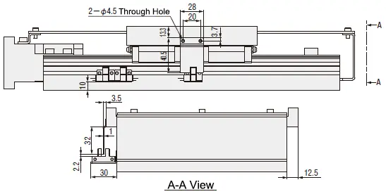
■Cover Specification Optical Sensor Dimensions Table
| Applicable Part Number | Code |
| E-KUAC 1510L/1520L | CW1 CW2 CW3 |
| E-KUAC 2010L/2020L |