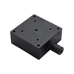
Manual Goniometer Stages Dovetail Type Single Axis
Brand :
MISUMI
Caution
Product Description
Product Overview
MISUMI E-GFSG Series Manual Goniometer Stages Dovetail Type Single Axis
Dimensional Drawing

Specifications Table
| Part Number | Top View | Main View | Side View | Stage Surface (MM) | Height of Rotation Center (mm) | Travel Distance | Travel Distance Per 1 Knob Rotation | Load Capacity (N) | Weight (kg) | |||||||
| TYPE | A-H | B | J | H1 | D | P | e | d1 | d2 | X | ||||||
| E-GFSG | 25-20 | 16.5 | 8.6 | 15 | 8 | 7 | 4 | 2.4 | 4 | 20 | 25x25 | 20±0.1 | ±15° | ≈2.0° | 19.6 | 0.04 |
| 25-35 | 16.5 | 8.6 | 15 | 8 | 7 | 4 | 2.4 | 4 | 20 | 35±0.1 | ±10° | ≈2.0° | 19.6 | 0.04 | ||
| 30-30 | 16 | 8.6 | 14 | 8 | 7 | 3.1 | 2.4 | 4 | 20 | 30x30 | 30±0.1 | ±10° | ≈2.06° | 9.8 | 0.04 | |
| 30-44 | 16 | 8.6 | 13 | 8 | 7 | 3.1 | 2.4 | 4 | 20 | 44±0.1 | ±10° | ≈1.5° | 9.8 | 0.04 | ||
| 40-25 | 16.5 | 10.5 | 15 | 8 | 9 | 2.5 | 3.4 | 6 | 32 | 40x40 | 25±0.1 | ±20° | ≈2.2° | 29.4 | 0.08 | |
| 40-40 | 19.5 | 10.6 | 20 | 13 | 9 | 4.9 | 3.4 | 6 | 32 | 40±0.1 | ±15° | ≈1.89° | 29.4 | 0.11 | ||
| 40-60 | 19.5 | 10.6 | 20 | 13 | 9 | 3.8 | 3.4 | 6 | 32 | 60±0.1 | ±10° | ≈1.33° | 29.4 | 0.11 | ||
| 50-50 | 18 | 8.6 | 18 | 12 | 7 | 4.2 | 3.4 | 6 | 40 | 50x50 | 50±0.1 | ±10° | ≈1.55° | 29.4 | 0.14 | |
| 50-68 | 18 | 8.6 | 18 | 12 | 7 | 3 | 3.4 | 6 | 40 | 68±0.1 | ±10° | ≈1.2° | 29.4 | 0.14 | ||
| 50-86 | 18.3 | 8.6 | 18 | 12 | 7 | 2.2 | 3.4 | 6 | 40 | 86±0.1 | ±8° | ≈0.97° | 29.4 | 0.14 | ||
| 60-35 | 19.5 | 10.7 | 25 | 13 | 9 | 6.9 | 4.5 | 8 | 50 | 60x60 | 35±0.1 | ±25° | ≈2.0° | 58.8 | 0.22 | |
| 60-60 | 19.7 | 10.7 | 20 | 13 | 9 | 3.3 | 4.5 | 8 | 50 | 60±0.1 | ±20° | ≈1.3° | 58.8 | 0.26 | ||
| 60-80 | 19.5 | 10.7 | 20 | 13 | 9 | 3.1 | 4.5 | 8 | 50 | 80±0.1 | ±15° | ≈1.0° | 58.8 | 0.26 | ||
| 80-100 | 25.5 | 10.7 | 30 | 18 | 9 | 7 | 4.5 | 8 | 70 | 80x80 | 100±0.1 | ±18° | ≈1.3° | 49 | 0.56 | |
| 80-130 | 25.5 | 10.7 | 30 | 18 | 9 | 5.6 | 4.5 | 8 | 70 | 130±0.1 | ±15° | ≈1.0° | 49 | 0.54 | ||
Product Features
Feature 1: The body is made of aluminum alloy to achieve light weight
Feature 2: Free combination of 2 axes based on actual needs, allowing for use in more scenarios.
Feature 3: The body surface is black anodized, effectively preventing reflection of light, especially suitable for use in optical field.
Feature 4: The arc-driven positioning stage has its rotation center located on the central vertical line of the positioning stage surface. Higher precision and lower price compared with existing products.
Feature 2: Free combination of 2 axes based on actual needs, allowing for use in more scenarios.
Feature 3: The body surface is black anodized, effectively preventing reflection of light, especially suitable for use in optical field.
Feature 4: The arc-driven positioning stage has its rotation center located on the central vertical line of the positioning stage surface. Higher precision and lower price compared with existing products.
Example of Use

Usage Method
■Installation Method of Rotary Stage

 The above diagram is for demonstration purpose only. Refer to each catalog or 3D data for detailed shapes and specifications of the positioning stage.
Precautions for Surface Precision of Mounting Part

 The above diagram is for demonstration purpose only. Refer to each catalog or 3D data for detailed shapes and specifications of the positioning stage.Precautions for Surface Precision of Mounting Part
Application Industries
| Electronics/Home Appliance | Automotive | Medical | ||
 |  |  | ||
| Smart Phones | Semiconductor | Lithium battery | ||
 |  |  |