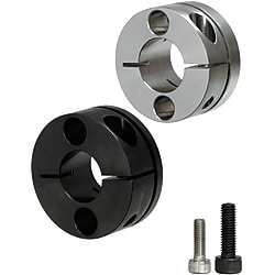
Shaft Supports-Compact Standard/Long type
Brand :
MISUMI
Caution
Product Description
This is an economy item, The price is cheaper than the MISUMI standard product.
Product Overview
A shaft support is a component that supports and fixes the shaft while also bearing a certain load.
Guide shaft supports are extremely widely used in the FA industry. They are typically used together with guide shafts and linear bearings to secure the guide shaft and ensure proper transmission.
Guide shaft supports are extremely widely used in the FA industry. They are typically used together with guide shafts and linear bearings to secure the guide shaft and ensure proper transmission.
Dimensional Drawing

Specifications Overview
・Material Specification table
 If there are requirements for rust prevention, give priority to products with surface treatment of electroless nickel plating.
For rust prevention methods, please refer to Technical Information
| Type |  Material Material |  Surface Treatment Surface Treatment |  Accessories Accessories | |
| Standard | Long Sleeve | |||
| E-STHMRB | E-STHMRBL | Equivalent to S45C | Black Oxide | 1 Hex Socket Head Cap Screw |
| E-STHMR | E-STHMRL | Electroless Nickel Plating | 1 Hex Socket Head Cap Screw (SUS) | |
 If there are requirements for rust prevention, give priority to products with surface treatment of electroless nickel plating.
For rust prevention methods, please refer to
 Technical Information
Specification Table
| Part Number | L | L1 | H | B | T | T1 | P | d1 | d2 | S | X | Y | M | d | R | |
| Type | DH8 | |||||||||||||||
| Standard Type E-STHMRB E-STHMR Long Sleeve E-STHMRBL E-STHMRL | 8 | 16 | - | 30 | 11 | 3.5 | - | 20 | 4.5 | 8 | 1.5 | 9.5 | 5 | 5 | 5.5 | 9 |
| 10 | 17 | - | 34 | 4.5 | - | 22 | 5.5 | 9.5 | 10 | 6 | ||||||
| 12 | 25 | 36 | 12.5 | 25 | 12 | |||||||||||
| 15 | 28 | 38 | 15.5 | 26 | 13 | |||||||||||
| 16 | 22 | 30 | 39 | 14 | 6 | 14 | 28 | 2 | 13.5 | 7 | 6 | 6.6 | 12 | |||
| 20 | 34 | 49 | 18 | 35 | 6.6 | 11 | 16 | 8 | ||||||||
| 25 | 38 | 54 | 22 | 40 | 19 | |||||||||||
| 30 | 24 | 40 | 59 | 8 | 24 | 45 | 22 | |||||||||
| D (Internal Diameter) | Outer Diameter (H) | ||
| Compact Example) E-STHMR | Open End · Standard Type Example) E-STHWR | Poor | |
| 8 | 30 | 39 | -9 |
| 10 | 34 | 49 | -15 |
| 12 | 36 | 52 | -16 |
| 15 | 38 | 56 | -18 |
| 16 | 39 | 56 | -17 |
| 20 | 49 | 64 | -15 |
| 25 | 54 | 69 | -15 |
| 30 | 59 | 79 | -20 |

Product Features
Feature 1: A simplified product that saves on support components. Space saving.
Feature 2: Suitable for precise positioning, making installation more convenient.
Feature 3: Compared to the standard type, the long sleeve type has a longer fitting section with the guide shaft, resulting in significantly improved retention and support.
Feature 4: the gap of the installation hole (through hole) can be used for fine adjustment, and the on-site positioning can be realized.
Feature 2: Suitable for precise positioning, making installation more convenient.
Feature 3: Compared to the standard type, the long sleeve type has a longer fitting section with the guide shaft, resulting in significantly improved retention and support.
Feature 4: the gap of the installation hole (through hole) can be used for fine adjustment, and the on-site positioning can be realized.
Precautions
(1) When locking the guide shaft with a set screw type guide shaft support, the guide shaft may be damaged due to the tightening of the set screw.
(2) Hex socket head cap screws are not included. For included screws, please refer to P.118 for additional processing.
(3) Whether the slot of the open-type linear shaft support is overcut depends on the size of the saw blade. 3D drawings are for reference only. (Overcut refers to the saw blade cutting through to the opposite side of the groove)
(2) Hex socket head cap screws are not included. For included screws, please refer to P.118 for additional processing.
(3) Whether the slot of the open-type linear shaft support is overcut depends on the size of the saw blade. 3D drawings are for reference only. (Overcut refers to the saw blade cutting through to the opposite side of the groove)
Example of Use

Equipment Name:
Stopper with Check Valve Component
Function:
The workpiece is placed on the chain conveyor for transfer. Use the cylinder to set the stopper handle to the raised position for standby, stopping the workpiece.
Use the cylinder to release the stopper and transfer the workpiece.
Function of shaft supports:
Fix the guide shaft with the guide shaft support for easy removal; related mechanisms can be reused.
For more information, please clickStopper with Check Valve Component.
Stopper with Check Valve Component
Function:
The workpiece is placed on the chain conveyor for transfer. Use the cylinder to set the stopper handle to the raised position for standby, stopping the workpiece.
Use the cylinder to release the stopper and transfer the workpiece.
Function of shaft supports:
Fix the guide shaft with the guide shaft support for easy removal; related mechanisms can be reused.
For more information, please click
Stopper with Check Valve Component.Application Industries
| Smart phone | Electronic & Electrical Appliances | Lithium battery | ||
 |  |  | ||
| Automotive | Robotics | Medical | ||
 |  |  |
Related Products


