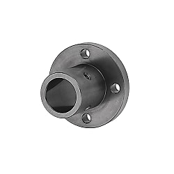
Shaft Supports Flanged Mount - Standard Sleeves/Long Sleeves - Standard Through/Tapped Mounting Holes
Brand :
MISUMI
Caution
Product Description
This is an economy item, The price is cheaper than the MISUMI standard product.
Product Overview
The shaft support can support and fix the shaft and also bear a certain load.
Dimensional Drawing
■ Standard

■ Long Guide Type


Specification Table
| Part Number | Mounting Hole Through Type | Mounting Hole Thread Type |  Material Material |  Surface Treatment Surface Treatment | Bore Diameter DH8 | |||
| Round Flange | Square Flange | Both Surfaces Cut Flange | Round Flange | Both Surfaces Cut Flange | ||||
| Standard | E-STHRB | E-STHSB | E-STHCB | E-STHRBT | E-STHCBT | General structural steel or carbon steel | Black Oxide | 3 to 50 |
| E-STHR | E-STHS | E-STHC | E-STHRT | E-STHCT | Electroless Nickel Plating | |||
| E-SSTHR | E-SSTHS | E-SSTHC | E-SSTHRT | E-SSTHCT | SUS304 | - | ||
| E-ATHR | E-ATHS | E-ATHC | - | - | Aluminum | Clear Anodized | ||
| E-BTHR | - | E-BTHC | - | - | Black Anodized | |||
| Long Guide Type | E-STHRBL | E-STHSBL | E-STHCBL | - | - | General structural steel or carbon steel | Black Oxide | |
| E-STHRL | E-STHSL | E-STHCL | - | - | Electroless Nickel Plating | |||
| E-SSTHRL | E-SSTHSL | E-SSTHCL | - | - | SUS304 | - | ||
 If there are requirements for rust prevention, give priority to products with electroless nickel plating surface treatment, aluminum alloy materials, or stainless steel SUS3 series materials.Hex socket bolts are not included. If bolts are required, please refer to the additional machining options at the bottom of the specifications table.When the fixed plate has low strength or is relatively thin, it is recommended to use the mounting hole screw type.
■ Dimension Specification Table
| Part Number | Sleeve Thickness (N) | L | L1 | D1 | H | T | ℓ | ℓ1 | M (Coarse Thread) | P | K | W | P1 | F | d1 | M1 (Coarse Thread) | ||||||
| Type | DH8 | |||||||||||||||||||||
| Standard Mounting Hole Through Type | 6 | +0.018 0 | 3 | 15 | - | 12 | 28 | 3.5 | 7 | - | M3 | 20 | 22 | 12 | 20 | - | 3.5 | - | ||||
| Round Flange | Square Flange | Both Surfaces Cut Flange | 8 | +0.022 0 | 2 | 16 | 12 | 28 | 5 | 10 | 20 | 22 | 16 | 20 | ||||||||
| E-STHRB | E-STHSB | E-STHCB | ||||||||||||||||||||
| E-STHR | E-STHS | E-STHC | 10 | 20 | 14 | 30 | 12 | M3 | 22 | 23 | 18 | 22 | 3.5 | - | ||||||||
| E-SSTHR | E-SSTHS | E-SSTHC | ||||||||||||||||||||
| E-ATHR | E-ATHS | E-ATHC | *1 | 12 | *2 | +0.027 0 | 24 | 30 | 16 | 36 | 6 | 15 | 15 | M4 | 26 | 28 | 20 | 26 | 4.5 | M4 | ||
| E-BTHR | E-BTHC | 15 | *2 | 2.5 | 30 | 20 | 40 | 18 | - | 30 | 32 | 24 | 30 | |||||||||
| Standard Mounting Hole Threaded Type (only for D size with *2 symbol) | *1 | 16 | *2 | 3 | 32 | 48 | 22 | 42 | 19 | 16 | 32 | 33 | 26 | 28 | 16 | |||||||
| E-STHRBT | E-STHCBT | 18 | 5 | 32 | - | 28 | 50 | 8 | 20 | - | M5 | 39 | 39 | 32 | 31 | 22 | 5.5 | M5 | ||||
| E-STHRT | E-STHCT | *1 | 20 | *2 | +0.033 0 | 4 | 32 | 48 | 28 | 50 | 8 | 20 | 16 | 39 | 39 | 32 | 31 | 22 | ||||
| E-SSTHRT | E-SSTHCT | *1 | 25 | *2 | 38 | 57 | 33 | 55 | 8 | 23 | 19 | 44 | 44 | 37 | 36 | 24 | ||||||
| Long Guide Type (only D size with *1 symbol) | *1 | 30 | *2 | 38 | 66 | 10 | 24 | 19 | M6 | 52 | 52 | 42 | 41 | 27 | 6.6 | M6 | ||||||
| E-STHRBL | E-STHSBL | E-STHCBL | 35 | +0.039 0 | 5 | 50 | - | 45 | 80 | 10 | 30 | - | 65 | 65 | 55 | 56 | 33 | 9 | M8 | |||
| E-STHRL | E-STHSL | E-STHCL | 40 | 10 | 60 | 90 | 10 | 75 | 75 | 65 | 65 | 38 | ||||||||||
| E-SSTHRL | E-SSTHSL | E-SSTHCL | 50 | 70 | 100 | 10 | 85 | 90 | 75 | 74 | 43 | |||||||||||
L1 and ℓ1 in the above table are the product dimensions for the long guide type guide shaft support.Mounting hole screw type is only applicable to D sizes marked with *2.The long guide type is only applicable to D dimensions marked with *1.Product Features
Feature 1: The inner diameter tolerance of the guide shaft support can still meet the H8 tolerance after surface treatment. When used together with the g6 tolerance guide shaft, the fit is worry-free.
Feature 2: For installation environments where the fixed plate has low strength (such as aluminum alloy) or the plate is thin and difficult to process threads, it is recommended to use the threaded mounting hole type of the standard guide shaft support for quick installation.
Feature 3: Compared to the standard type, the long guide type has a longer fitting section with the guide shaft, which greatly improves retention and support.
Feature 4: the gap of the installation hole (through hole) can be used for fine adjustment, and the on-site positioning can be realized.
Feature 5: Various flange shapes are available, including round, square, and compact flange types. Choosing the compact flange type enables space-saving designs.
Feature 2: For installation environments where the fixed plate has low strength (such as aluminum alloy) or the plate is thin and difficult to process threads, it is recommended to use the threaded mounting hole type of the standard guide shaft support for quick installation.
Feature 3: Compared to the standard type, the long guide type has a longer fitting section with the guide shaft, which greatly improves retention and support.
Feature 4: the gap of the installation hole (through hole) can be used for fine adjustment, and the on-site positioning can be realized.
Feature 5: Various flange shapes are available, including round, square, and compact flange types. Choosing the compact flange type enables space-saving designs.
Precautions
When locking the guide shaft with a set screw type guide shaft support, the locking action of the set screw may damage the guide shaft.
Slit shaft support can be connected without damaging the shaft.
Slit shaft support can be connected without damaging the shaft.
Example of Use

Equipment Name:
Simple Manual Characteristic Inspection Mechanism
Key Points of Mechanism Design:
Manual inspection fixture for electrical characteristics, suitable for small batch production. Pull out the workpiece guide rail and move it to the fixed inspection position after placing the workpiece. Use the operating lever to control the lifting and lowering of the inspection device to check the electrical characteristics of the workpiece.
Function of shaft supports:
shaft supports are used to fix the inspection mechanism for easy disassembly, and related mechanisms can be reused.
For more information, please click here.
here.
Simple Manual Characteristic Inspection Mechanism
Key Points of Mechanism Design:
Manual inspection fixture for electrical characteristics, suitable for small batch production. Pull out the workpiece guide rail and move it to the fixed inspection position after placing the workpiece. Use the operating lever to control the lifting and lowering of the inspection device to check the electrical characteristics of the workpiece.
Function of shaft supports:
shaft supports are used to fix the inspection mechanism for easy disassembly, and related mechanisms can be reused.
For more information, please click
 here.
here.Application Industries


Related Products
| Guide shaft Straight bar type | Linear bearing with flange Single liner standard | Post Clamp | ||
 |  |  | ||
| Typical model: SFJ6-100 | Typical model: LHFC8 | Typical model: KDST20 |
Related Documents