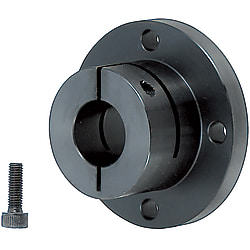
Shaft Supports - Flanged Mount with Slit, Standard Sleeves/Long Sleeves
Brand :
MISUMI
Caution
Product Description
This is an economy item, The price is cheaper than the MISUMI standard product.
Product Overview
A shaft support is a component that supports and fixes the shaft while also bearing a certain load.
Product Feature
Product Feature
Feature 1: Compared to the standard type, the long guide type has a longer fitting section with the guide shaft, resulting in significantly improved holding and supporting force.
Feature 2: Various flange shapes are available, including round, square, and compact flange types; choosing the compact flange type enables space-saving designs.
Feature 3: the gap of the installation hole (through hole) can be used for fine adjustment, and the on-site positioning can be realized.
Feature 2: Various flange shapes are available, including round, square, and compact flange types; choosing the compact flange type enables space-saving designs.
Feature 3: the gap of the installation hole (through hole) can be used for fine adjustment, and the on-site positioning can be realized.
Dimensional Drawing


Specification Table
■ Material Specification Table
| Type |  Material Material |  Surface Treatment Surface Treatment |  Accessories Accessories | Bore Diameter DH8 | |||
| Part Number | Round Flange | Square Flange | Both Surfaces Cut Flange | ||||
| Open Standard | E-STHWRB | E-STHWSB | E-STHWCB | General structural steel or carbon steel | Black Oxide | 1 Hex Socket Head Cap Screw | 8 to 50 |
| E-STHWR | E-STHWS | E-STHWC | Electroless Nickel Plating | 1 Hex Socket Head Cap Screw (SUS) | |||
| E-SSTHWR | E-SSTHWS | E-SSTHWC | SUS304 | - | |||
| Open Long Guide Type | E-STHWRBL | E-STHWSBL | E-STHWCBL | General structural steel or carbon steel | Black Oxide | 2 Hex Socket Head Cap Screws | |
| E-STHWRL | E-STHWSL | E-STHWCL | Electroless Nickel Plating | 2 Hex Socket Head Cap Screws (SUS) | |||
| E-SSTHWRL | E-SSTHWSL | E-SSTHWCL | SUS304 | - | |||
 If there are requirements for rust prevention, give priority to products with surface treatment of electroless nickel plating or those made of stainless steel SUS304 series materials.
■ Size Specification Table Bracket Type Open Standard Type
| Part Number | D1 | H | Sleeve Thickness (N) | L | T | B | S1 | X | P | K | W | P1 | F | S | Y | d1 | d2 | d | M (Coarse Thread) | Accessory Bolt M × Length | ||
| Type | DH8 | |||||||||||||||||||||
| Round Flange Type E-STHWRB E-STHWR E-SSTHWR Method Flange Type E-STHWSB E-STHWS E-SSTHWS Compact Flanged E-STHWCB E-STHWC E-SSTHWC | 8 | +0.022 0 | 25 | 39 | 8.5 | 18 | 5 | 10 | 1.5 | 7.5 | 32 | 30 | 27 | 25 | 20 | 1.5 | 3.5 | 7.5 | 4.6 | 3.5 | M4 | M4 × 10 |
| 10 | 30 | 49 | 10 | 20 | 5 | 10 | 10 | 40 | 38 | 32 | 33 | 23 | 3 | 9 | 5.6 | 4.5 | M5 | M5 × 10 | ||||
| 12 | +0.027 0 | 32 | 52 | 10 | 22 | 6 | 10 | 11 | 42 | 40 | 34 | 35 | 25 | 4 | M5 × 12 | |||||||
| 15 | 35 | 56 | 10 | 27 | 6 | 12 | 12 | 46 | 44 | 37 | 37 | 27 | 5 | 5.5 | ||||||||
| 16 | 9.5 | 30 | 6 | 12 | 12 | 46 | 44 | 37 | 37 | 27 | 5 | |||||||||||
| 20 | +0.033 0 | 40 | 64 | 10 | 32 | 8 | 12 | 2 | 14 | 52 | 50 | 42 | 43 | 30 | 6 | 6.6 | M5×16 | |||||
| 25 | 45 | 69 | 10 | 38 | 8 | 15 | 17 | 57 | 54 | 47 | 46 | 34 | 6 | |||||||||
| 30 | 55 | 79 | 12.5 | 40 | 10 | 15 | 20 | 67 | 60 | 57 | 50 | 45 | 10 | 12 | 6.6 | M6 | M6×20 | |||||
| 35 | +0.039 0 | 60 | 94 | 12.5 | 48 | 10 | 15 | 23 | 77 | 71 | 66 | 58 | 50 | 12 | 9 | |||||||
| 40 | 70 | 104 | 15 | 55 | 12 | 18 | 26 | 87 | 81 | 76 | 67 | 55 | 13 | 14 | 9 | M8 | M8 × 26 | |||||
| 50 | 85 | 119 | 17.5 | 65 | 12 | 22 | 32 | 102 | 94 | 91 | 82 | 60 | 16 | 18 | 11 | M10 | M10 × 32 | |||||
■ Size Specification Table Bracket Type Open Long Guide Type
| Part Number | D1 | H | Sleeve Thickness (N) | L | T | B | S1 | X | P | K | W | P1 | F | S | Y | d1 | d2 | d | M (Coarse Thread) | Accessory Bolt M × Length | ||||
| Type | DH8 | |||||||||||||||||||||||
| Round Flange | Square Flange | Both Surfaces Cut Flange | 12 | 0.027 0 | 32 | 52 | 10 | 33 | 6 | 20 | 1.5 | 11 | 42 | 40 | 34 | 35 | 25 | 1.5 | 4 | 9 | 5.6 | 4.5 | M5 | M5 × 12 |
| 16 | 35 | 56 | 9.5 | 45 | 24 | 12 | 46 | 44 | 37 | 37 | 27 | 5 | 5.5 | |||||||||||
| E-STHWRBL | E-STHWSBL | E-STHWCBL | 20 | +0.033 0 | 40 | 64 | 10 | 48 | 8 | 2 | 14 | 52 | 50 | 42 | 43 | 30 | 6 | 6.6 | M5×16 | |||||
| E-STHWRL | E-STHWSL | E-STHWCL | 25 | 45 | 69 | 57 | 30 | 17 | 57 | 54 | 47 | 46 | 34 | |||||||||||
| E-SSTHWRL | E-SSTHWSL | E-SSTHWCL | 30 | 55 | 79 | 12.5 | 60 | 10 | 20 | 67 | 60 | 57 | 50 | 45 | 10 | 12 | 6.6 | M6 | M6×20 | |||||
| 35 | +0.039 0 | 60 | 94 | 72 | 23 | 77 | 71 | 66 | 58 | 50 | 12 | 9 | ||||||||||||
| 40 | 70 | 104 | 15 | 82.5 | 12 | 36 | 26 | 87 | 81 | 76 | 67 | 55 | 13 | 14 | 9 | M8 | M8 × 26 | |||||||
| 50 | 85 | 119 | 17.5 | 97.5 | 44 | 32 | 102 | 94 | 91 | 82 | 60 | 16 | 18 | 11 | M10 | M10 × 32 | ||||||||
Precautions
(1) Open type: The tolerance H8 of the mounting hole D refers to the tolerance before the slot is machined. After slot machining, due to the release of internal stress, the tolerance may increase to around H9.
②It is recommended that the shaft support is matched with shaft with tolerance of f8/h5/g6. For more details, click here.
here.
(3) For anti-rust performance and maintenance of metal materials and surface treatment, please clickhere.
(4) Whether the slotting of the open-type guide shaft support is overcut depends on the size of the saw blade. 3D drawings are for reference only. (Overcut refers to the saw blade cutting through to the opposite side of the groove)
②It is recommended that the shaft support is matched with shaft with tolerance of f8/h5/g6. For more details, click
 here.
here.(3) For anti-rust performance and maintenance of metal materials and surface treatment, please click
here.(4) Whether the slotting of the open-type guide shaft support is overcut depends on the size of the saw blade. 3D drawings are for reference only. (Overcut refers to the saw blade cutting through to the opposite side of the groove)
Example of Use

Organization Name: Hole Slot Depth Inspection Fixture
Function of the Organization:
Correct workpiece positioning can be continuously performed and the depth of workpiece hole groove can be checked manually.
Function of shaft supports:
shaft supports are used to fix the inspection mechanism for easy disassembly.
For more information, please clickhere.
Function of the Organization:
Correct workpiece positioning can be continuously performed and the depth of workpiece hole groove can be checked manually.
Function of shaft supports:
shaft supports are used to fix the inspection mechanism for easy disassembly.
For more information, please click
here.Application Industries
<


Related Products


Related Documents

Overview · Features
■ Features: When clamping the guide shaft, connection can be made without damaging the guide shaft. Suitable for places with frequent loading and unloading.