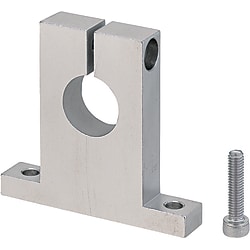
Shaft Supports T-Shaped with Slit
Brand :
MISUMI
Caution
Product Description
This is an economy item, The price is cheaper than the MISUMI standard product.
Product Overview
The shaft support can support and fix the shaft and also bear a certain load.
Dimensional Drawing

Specification Table
■ Material Specification Table
| Height H Selectable |  Material Material |  Surface Treatment Surface Treatment |  Accessories Accessories | Inner Diameter D |
| E-SHSTB | General structural steel or carbon steel | Black Oxide | 1 Hex Socket Head Cap Screw | 8 to 30 |
| E-SHSTM | Electroless Nickel Plating | 1 Hex Socket Head Cap Screw (SUS) | ||
| E-SHSTA | Aluminum | Clear Anodized |
 If there are requirements for rust prevention, give priority to products with surface treatment of electroless nickel plating, or those made of SUS3 series stainless steel or aluminum alloy.
For surface treatment and anti-rust methods, please refer to
 Anti-rust performance and maintenance of metal materials and surface treatment.
■ Dimension Specification Table
| Part Number | H | L | H1 | T | S | W | L1 | d | E | Fastening bolt M | d2 | d1 | ℓ | C | |
| Type | D | Height selection type | |||||||||||||
| Height H Selection Type E-SHSTB E-SHSTM E-SHSTA | |||||||||||||||
| 8 | 10 15 20 25 30 40 | 42 | H+16 | 10 | 6 | 18 | 30 | 4.5 | 11 | M4 Through Hole | 4.5 | 8 | 4.5 | 2 | |
| 10 | 10 15 20 25 30 | ||||||||||||||
| 12 | H+18 | 13 | |||||||||||||
| 15 | 15 20 25 30 | 54 | H+20 | 30 | 42 | 15 | M4 Depth 8 | ||||||||
| 16 | 15 20 25 30 40 | ||||||||||||||
| 20 | 20 25 30 40 50 60 | 67 | H+26 | 16 | 8 | 35 | 50 | 6.6 | 18 | M6 Through Hole | 6.6 | 11 | 6.5 | ||
| 25 | 20 25 30 40 50 60 | H+28 | 21 | ||||||||||||
| 30 | 25 30 40 50 60 | 85 | H+33 | 20 | 10 | 45 | 65 | 9 | 24 | M8 Depth 16 | 9 | 14 | 9 | 3 | |
Product Features
Feature 1: T-shaped shaft supports can be installed and used even if the surrounding space is small. T shape is more suitable for the situation of small front and back space.
Feature 2: slit shaft support can be connected without damaging the shaft.
Feature 3: The inner diameter of the T-type shaft support varies from 6 to 30 (please refer to the catalog for actual size). If you have special height requirements, please select the height-specified type of guide shaft support.
Feature 4: the gap of the installation hole (through hole) can be used for fine adjustment, and the on-site positioning can be realized.
Feature 2: slit shaft support can be connected without damaging the shaft.
Feature 3: The inner diameter of the T-type shaft support varies from 6 to 30 (please refer to the catalog for actual size). If you have special height requirements, please select the height-specified type of guide shaft support.
Feature 4: the gap of the installation hole (through hole) can be used for fine adjustment, and the on-site positioning can be realized.
Precautions
1. After machining the mounting hole D to H8 tolerance, if a slot is machined afterward, the tolerance may increase to around H9 due to the additional processing.
2. If there are requirements for rust prevention, give priority to products with surface treatment of electroless nickel plating, or those made of SUS3 series stainless steel or aluminum alloy.
2. If there are requirements for rust prevention, give priority to products with surface treatment of electroless nickel plating, or those made of SUS3 series stainless steel or aluminum alloy.
Example of Use

■ Organization Name
Check the input table.
■ Mechanism Function
A component that transports the item to be inspected to the inspection position in order to check the image at a specific location on the circuit board.
After obtaining the image data from the camera, use the cylinder to return to the front of the sliding guide rail.
Loading and unloading of workpieces is performed on the loaders of the previous and subsequent processes.
■ Function of the Guide Shaft Support
The guide shaft support is used to fix the inspection mechanism, making it easy to disassemble and allowing related mechanisms to be reused.
For more information, please click Inspection Input Table.
Check the input table.
■ Mechanism Function
A component that transports the item to be inspected to the inspection position in order to check the image at a specific location on the circuit board.
After obtaining the image data from the camera, use the cylinder to return to the front of the sliding guide rail.
Loading and unloading of workpieces is performed on the loaders of the previous and subsequent processes.
■ Function of the Guide Shaft Support
The guide shaft support is used to fix the inspection mechanism, making it easy to disassemble and allowing related mechanisms to be reused.
For more information, please click Inspection Input Table.
Application Industries
| Smart phone | Electronic & Electrical Appliances | Lithium battery | ||
 |  |  | ||
| Automotive | Robotics | Medical | ||
 |  |  |
Related Products
| Bearing Housing Assembly Single Bearing Type with Retaining Ring | Shaft Supports T Shape Slit | Post Clamp | ||
 |  |  | ||
| Typical model: BGRAB6000ZZ | Typical model: SHSTM8-25 | Typical model: KDST20 |
Related Documents