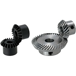
Bevel Gear, Pressure Angle 20°
Brand :
MISUMI
Caution
Product Description
Product Overview
Bevel gears are used to transmit motion and power between two intersecting shafts. In general machinery, the angle between the two shafts of bevel gears is 90°.
Dimensional Drawing

| Shaft Hole Specifications | ||
| Round Hole | Round Hole+Tapped Hole | Keyway Hole + Tapped Hole |
 |  |  |
Material Table
| Type |  Material Material |  Surface Treatment Surface Treatment |  Accessories Accessories | Module | Number of Teeth | ||||
| Straight Gear Type | Spiral Type | ||||||||
| Round Hole | Round Hole + Tapped Hole | Keyway Hole + Tapped Hole | Round Hole + Tapped Hole | Keyway Hole + Tapped Hole | |||||
| E-KGEASH | E-KGEAST | E-KGEASK | E-KGEAPT | E-KGEAPK | General structural steel or carbon steel | - | Set screw (tempered steel, black oxide film) | 1.0 1.5 2.0 | 18 to 40 |
| E-KGEASHB | E-KGEASTB | E-KGEASKB | E-KGEAPTB | E-KGEAPKB | Black Oxide Film | ||||
| E-KGEASHG | E-KGEASTG | E-KGEASKG | E-KGEAPTG | E-KGEAPKG | Electroless Nickel Plating | ||||
| E-KGHS | E-KGTS | E-KGKS | - | - | Stainless Steel | - | Set Screw (Stainless Steel) | ||
 If there are requirements for rust prevention, give priority to products with surface treatment of electroless nickel plating or those made of stainless steel.When selecting the shaft hole specification without thread type, the fixing screws are not included.For detailed dimensions of the keyway hole, please refer to
  Technical Data. The position relationship between the keyway and the teeth is not fixed.
Processing Method
| Material |  | Cut-off | | Turning |
 |  |  | ||
| Purchase raw materials from material manufacturers and add them to inventory. | Select a rod with a diameter larger than the finished product. Cut to the appropriate size using a cutting machine. | Place the cut blank on the lathe for machining. Form the shape of the gear and make a gear blank. | ||
 | ||||
| Apply anti-rust oil |  | Deburring | | Hobbing |
 |  |  | ||
| Apply rust preventive oil evenly to prevent product rusting. | Remove excess burrs from the gear. To ensure the service life of the gear. | Place the gear blank on the hobbing machine for processing. After hobbing, a large amount of burrs will appear on the gear tooth end face. |
Alteration
| Alterations | Additional Processing for Set Screw Holes | |||
| Code | KC90 | KC120 | ||
| Spec. |  | Add one more set screw hole at the 90° position. X round hole type not applicable |  | Add one more set screw hole at the 120° position. X round hole type not applicable |
Specification Table
■ Straight Gear Type
■ Spiral Type (Helix Angle 35°)
 When selecting paired gears, please note that you need to refer to the paired nominal code in the table above to assist with selection.
KGHS (stainless steel shaft hole specification: round hole) No module 1.0.
Gears are sold individually, not as pairs. Attention!
When using the spiral type, please combine L and R.
When selecting a shaft hole diameter of 10 with keyway hole + tapped hole and a keyway width of 4.0 mm (height 1.8 mm), please specify the P dimension as 10K.  Technical data.
 Nominal model Nominal model |  Shaft Hole Diameter PH7, Unit: 1 mm Shaft Hole Diameter PH7, Unit: 1 mm | Number of Teeth | R (Gear Ratio) | Matching Nominal Code | B | H | d | D | S | E | L | G | ℓ1 | ℓ2 | L1 | A° | M (Coarse Thread) | |||
 Type Type |  Module Module | Round Hole Round Hole+Tapped Hole | Keyway Hole + Tapped Hole | |||||||||||||||||
Round Hole | 1 | 2020 | 6·8 | 8 | 20 | 1:01 | 2020 | 4.3 | 16 | 20 | 21.41 | 11.8 | 21 | 14.53 | 11.71 | 9 | 4.5 | 13 | 49° 3' | M4 |
| 2525 | 6·8·10 | 8·10 | 25 | 2525 | 5.3 | 20 | 25 | 26.41 | 15 | 23 | 14.7 | 11.21 | 8 | 4 | 13 | 48° 51' | M4 | |||
| 3030 | 8·10·12 | 8·10·12 | 30 | 3030 | 6.2 | 22 | 30 | 31.41 | 19.4 | 26 | 15.89 | 11.71 | 8.9 | 4.5 | 14.5 | 47° 42' | M4(M5) | |||
| 2040 | 6·8 | 8 | 20 | 1:02 | 4020 | 5.7 | 16 | 20 | 21.79 | 12.1 | 29.6 | 15.03 | 10.05 | 8.6 | 4 | 14 | 29° 8' | M4 | ||
| 4020 | 8·10·12 | 8·10·12 | 40 | 2040 | 5.7 | 25 | 40 | 40.89 | 28.4 | 21.8 | 15.02 | 12.69 | 8 | 4 | 13 | 66° 0' | M4(M5) | |||
| 1.5 | 2020 | 10·12 | 10·12 | 20 | 1:01 | 2020 | 6.8 | 24 | 30 | 32.12 | 17.7 | 28 | 18.53 | 14.06 | 10 | 5 | 16.5 | 49° 3' | M4 | |
| 2525 | 10 to 14 | 10 to 14 | 25 | 2525 | 7.5 | 30 | 37.5 | 39.62 | 23.7 | 34 | 21.26 | 16.31 | 11.5 | 5 | 19 | 48° 51' | M4 | |||
| 3030 | 12 to 16 | 12 to 16 | 30 | 3030 | 9.3 | 33 | 45 | 47.12 | 29.6 | 38 | 22.83 | 16.56 | 12.34 | 6 | 21 | 47° 42' | M5 | |||
| 1836 | 8·10·12 | 8 | 18 | 1:02 | 3618 | 9.8 | 22 | 27 | 29.68 | 12.2 (12.1) | 40.74 | 22.96 | 14.41 | 12.5 | 6 | 21 | 29° 25' | M4 | ||
| 3618 | 10 to 15 | 10 to 15 | 36 | 1836 | 9.8 | 30 | 54 | 55.34 | 34.3 | 26.75 | 18.54 | 14.59 | 10 | 5 | 15.5 | 66° 17' | M5 | |||
| 2 | 2020 | 12 to 14 | 12 to 14 | 20 | 1:01 | 2020 | 8.5 | 34 | 40 | 41.32 | 23.9 | 37 | 24 | 18.41 | 14 | 7 | 21 | 49° 3' | M5 | |
| * 2525 | 25 | 2525 | 10.5 | 42 | 50 | 51.33 | 32.3 | 40 | 23.34 | 16.41 | 10.99 | 5 | 21 | 48° 51' | M5 | |||||
| 3030 | 16 to 18 | 16 to 18 | 30 | 3030 | 12.4 | 44 | 60 | 61.36 | 38.9 | 51 | 30.77 | 22.41 | 16.79 | 8 | 28 | 47° 42' | M6 | |||
| 1836 | 10 | 10 | 18 | 1:02 | 3618 | 12.6 | 28 | 36 | 37.81 | 19.1 | 53.12 | 29 | 18.01 | 15.12 | 7 | 27 | 29° 25' | M4 | ||
| 3618 | 12 to 14 | 12 to 14 | 36 | 1836 | 12.6 | 36 | 72 | 72.15 | 47.6 | 35.21 | 24.07 | 19 | 13 | 6.5 | 21 | 66° 17' | M5 | |||
■ Spiral Type (Helix Angle 35°)
| Part Number | Nominal model | Shaft Hole Diameter PH7, Unit: 1 mm |  Twisting Direction Twisting Direction | Number of Teeth | R (Gear Ratio) | Matching Nominal Code | B | H | d | D | S | E | L | G | ℓ1 | ℓ2 | L1 | A° | M (Coarse Thread) | ||
| Type | Module | Round Hole +Tapped Hole | Keyway Hole + Tapped Hole | ||||||||||||||||||
| Round Hole + Tapped Hole E-KGEAPT E-KGEAPTB E-KGEAPTG Keyway Hole + Tapped Hole E-KGEAPK E-KGEAPKB E-KGEAPKG | 1 | 2020 | 6·8 | 8 | L R (Left)(Right) | 20 | 1:01 | 2020 | 4.5 | 16 | 20 | 21.12 | 11.3 | 21 | 14.43 | 11.56 | 9 | 4.5 | 13 | 50° 31' | M4 |
| 3030 | 10·12 | 10·12 | 30 | 3030 | 6.2 | 22 | 30 | 31.09 | 19.4 | 26 | 15.67 | 11.54 | 9 | 4.5 | 14.5 | 48° 21' | M5 | ||||
| 2040 | 8·10·12 | 8 | L (Left) | 20 | 1:02 | 4020 | 5.7 | 16 | 20 | 21.87 | 12.1 | 29.6 | 15 | 10.07 | 8.6 | 4 | 14 | 30° 13' | M4 | ||
| 4020 | 10·12 | 10·12 | R (Right) | 40 | 2040 | 5.7 | 25 | 40 | 40.41 | 28.4 | 21.8 | 14.57 | 12.21 | 8 | 4 | 13 | 65° 36' | M5 | |||
| 1.5 | 2020 | 10·12 | 10·12 | L R (Left)(Right) | 20 | 1:01 | 2020 | 7 | 24 | 30 | 31.85 | 17.2 | 28 | 18.44 | 13.93 | 10 | 5 | 16.5 | 50° 5' | M4 | |
| 3030 | 12 to 16 | 12 to 16 | 30 | 3030 | 9.3 | 33 | 45 | 46.79 | 29.7 | 38 | 22.64 | 16.4 | 12 | 6 | 21 | 47° 54' | M5 | ||||
| 1836 | 8·10·12 | 8 | L (Left) | 18 | 1:02 | 3618 | 9.8 | 22 | 27 | 30.09 | 12.2 | 40.74 | 22.96 | 14.51 | 12.49 | 6 | 21 | 30° 44' | M4 | ||
| 3618 | 10 to 15 | 10 to 15 | R (Right) | 36 | 1836 | 9.8 | 30 | 54 | 54.76 | 34.3 | 26.75 | 18.01 | 14.01 | 9 | 4.5 | 15.5 | 65° 57' | M5 | |||
When selecting paired gears, please note that you need to refer to the paired nominal code in the table above to assist with selection.KGHS (stainless steel shaft hole specification: round hole) No module 1.0.Gears are sold individually, not as pairs. Attention!When using the spiral type, please combine L and R.When selecting a shaft hole diameter of 10 with keyway hole + tapped hole and a keyway width of 4.0 mm (height 1.8 mm), please specify the P dimension as 10K. Technical data.