Spur Gear Pressure Angle 20° Module 3.0

Brand :
MISUMI
Caution
Product Description
Product Overview
A gear is a product with teeth added around the circumference of a drive wheel. Gear transmission mechanisms are widely used for transmitting rotational motion, rotational speed, and rotational direction.
Product Feature
Feature 1: Spur gears can provide high transmission power, and the instantaneous transmission ratio is stable, making them suitable for high-torque transmission and conveying.
Feature 2: Spur gears have a fixed center distance and long service life, making them suitable for compact and highly reliable mechanisms.
Feature 3: MISUMI brand economy spur gears feature high-precision tooth profiles, with a precision grade of GB/T 10095-2008 Grade 8; shaft hole diameter tolerance is H7.
Feature 4: Characteristics of Gear Mechanisms
Feature 2: Spur gears have a fixed center distance and long service life, making them suitable for compact and highly reliable mechanisms.
Feature 3: MISUMI brand economy spur gears feature high-precision tooth profiles, with a precision grade of GB/T 10095-2008 Grade 8; shaft hole diameter tolerance is H7.
Feature 4: Characteristics of Gear Mechanisms
Advantages:
(1) No transmission delay, not prone to skipping or slipping teeth
(2) Relatively free change of transmission direction
(3) Relatively free adjustment of transmission speed
(4) Suitable for high-power transmission, as well as high-load and high-torque transmission
(5) Less affected by temperature, humidity, or oily environments
(6) Suitable for compact space designs
(1) No transmission delay, not prone to skipping or slipping teeth
(2) Relatively free change of transmission direction
(3) Relatively free adjustment of transmission speed
(4) Suitable for high-power transmission, as well as high-load and high-torque transmission
(5) Less affected by temperature, humidity, or oily environments
(6) Suitable for compact space designs
Disadvantages:
(1) Prone to noise
(2) Lubricating oil required for maintenance
(3) Safety protection devices required
(1) Prone to noise
(2) Lubricating oil required for maintenance
(3) Safety protection devices required
Dimensional Drawing

 Threading of shaft holes is not possible for Type A
 Set Screw is not included in Untapped type products.Selectable gear shapes differ depending on the number of teeth.
  Please click
  Detailed Dimensions of Keyway.The position relationship between the keyway and the teeth is not fixed.A round shaft hole specification does not include a threaded hole.
Specification Table
Material Specifications
 Gear accuracy: GB/T 10095-2008 Grade 8.
If there are requirements for rust prevention, give priority to products made of SUS304.
Specification Table
When selecting a shaft hole with keyway + threaded hole, shaft hole diameter 10, and keyway width 4.0 mm (height 1.8 mm), please specify the P dimension as 10K. For details, please refer to Keyway Specifications
*1 The allowable transmission force in the table is a reference value calculated under normal conditions. For details, please refer to Gear Transmission Power Calculation
For custom specifications, please contact us.
| Type |  Material Material |  Surface Treatment Surface Treatment |  Accessories Accessories | |
| Round Hole | Keyway Hole Keyway Hole + Threaded Hole | |||
| E-GEAHB | E-GEAKB | Equivalent to S45C | - | Set Screw (SCM435·Ferroferric Oxide Protective Film) |
| E-GEAHBB | E-GEAKBB | Ferroferric Oxide Protective Film | ||
| E-GEAHS | E-GEAKS | SUS304 | - | Set Screw (Equivalent to SUS304) |
 Gear accuracy: GB/T 10095-2008 Grade 8.If there are requirements for rust prevention, give priority to products made of SUS304.
Specification Table
| Part Number | Number of Teeth | Thickness B | Gear Shape Type | Shaft Hole Diameter PH7 Specified Unit: 1 mm | d Pitch Circle Diameter | D Addendum Circle Diameter | G Dedendum Circle Diameter | H | L | ℓ1 | ℓ2 | M (Coarse Thread) | * 1Permissible Transmittable Torque (N⋅m) Bending Strength | |||
| Type | Module Number | Round Hole | Keyway Hole (Type A) Keyway Hole + Threaded Hole (Type B) | S45C | SUS304 | |||||||||||
| (Selectable Gear Shape) Round Hole (Type A · Type B) E-GEAHB E-GEAHBB E-GEAHS Keyway hole (Type A) Keyway Hole + Threaded Hole (Type B) E-GEAKB E-GEAKBB E-GEAKS | 3.0 | 12 | 30 | A B | 8 to 17 | 8N·10N to 12N | 36 | 42 | 28.5 | 27 | 48 | 18 | 9 | M5 | 66.66 | 38.04 |
| 14 | 8 to 22 | 8N·10N to 16N | 42 | 48 | 34.5 | 32 | 86.33 | 49.27 | ||||||||
| 15 | 8 to 24 | 8N·10N to 19N | 45 | 51 | 37.5 | 35 | 96.7 | 55.18 | ||||||||
| 16 | 8 to 28 | 8N·10N to 23N | 48 | 54 | 40.5 | 40 | 107.1 | 61.12 | ||||||||
| 18 | 8 to 32 | 8N·10N to 27N | 54 | 60 | 46.5 | 44 | M6 | 128.5 | 73.33 | |||||||
| 19 | 8 to 33 | 8N·10N to 28N | 57 | 63 | 49.5 | 45 | 139.28 | 79.48 | ||||||||
| 20 | 8 to 38 | 8N·10N to 33N | 60 | 66 | 52.5 | 50 | 150.49 | 85.88 | ||||||||
| 22 | 8 to 42 | 8N·10N to 36N | 66 | 72 | 58.5 | 54 | 173.02 | 98.74 | ||||||||
| 24 | 8 to 46 | 8N·10N to 39N | 72 | 78 | 64.5 | 58 | 195.6 | 111.62 | ||||||||
| 25 | 8 to 48 | 8N·10N to 40N | 75 | 81 | 67.5 | 60 | 207.33 | 118.31 | ||||||||
| 26 | 10 to 53 | 10N to 44N | 78 | 84 | 70.5 | 65 | 219.36 | 125.18 | ||||||||
| 28 | 10 to 58 | 10N to 47N | 84 | 90 | 76.5 | 70 | 243.41 | 138.9 | ||||||||
| 30 | 10 to 60 | 10N to 50N | 90 | 96 | 82.5 | 75 | 266.4 | 152.02 | ||||||||
| 32 | 96 | 102 | 88.5 | 288.88 | 164.85 | |||||||||||
| 34 | 12 to 63 | 12N to 50N | 102 | 108 | 94.5 | 80 | 315.62 | 180.11 | ||||||||
| 35 | 105 | 111 | 97.5 | 327.41 | 186.84 | |||||||||||
| 36 | 108 | 114 | 100.5 | 337.93 | 192.84 | |||||||||||
| 40 | 12 to 65 | 120 | 126 | 112.5 | 85 | 386.49 | 220.55 | |||||||||
| 42 | 20 to 65 | 20N to 50N | 126 | 132 | 118.5 | 411.47 | 234.81 | |||||||||
| 45 | 135 | 141 | 127.5 | 449.84 | 256.7 | |||||||||||
| 48 | 25 to 68 | 25N to 50N | 144 | 150 | 136.5 | 487.2 | 278.02 | |||||||||
| 50 | 150 | 156 | 142.5 | 511.77 | 292.04 | |||||||||||
When selecting a shaft hole with keyway + threaded hole, shaft hole diameter 10, and keyway width 4.0 mm (height 1.8 mm), please specify the P dimension as 10K. For details, please refer to Keyway Specifications*1 The allowable transmission force in the table is a reference value calculated under normal conditions. For details, please refer to Gear Transmission Power CalculationFor custom specifications, please contact us.Usage Method
■ Intended Use for Spur Gears
Example of Use| Type of Transmission | Description | Transmission Diagram (Simple) | Representative Transmission Methods | Representative Types of Transmission Pairings |
| Parallel Transmission | Parallel transmission of rotation/power between two axes with meshing gears |  |  | Spur Gear + Spur Gear Helical Gear + Helical Gear Herringbone Gear + Herringbone Gear Spur Gear + Internal Gear Helical Gear + Internal Helical Gear |
| Linear Transmission | Rotational displacement/power transmitted linearly, or linear displacement/power transmitted rotationally |  |  | Spur Gear + Spur Rack Helical Gear + Helical Rack |

Precautions
(1) If there are requirements for rust prevention, give priority to products made of SUS304.
Please refer to Surface Treatment and Rust Prevention Methods
(2) When gears are used together, there will be backlash. The gear position relationship needs to be adjusted according to the on-site assembly situation to achieve optimal performance.
(3) For shaft hole specifications, when selecting the non-threaded type, the fixing screws are not included.
(4) The positional relationship between the keyway and the gear teeth is not fixed.
Please refer to
 Surface Treatment and Rust Prevention Methods
(2) When gears are used together, there will be backlash. The gear position relationship needs to be adjusted according to the on-site assembly situation to achieve optimal performance.
(3) For shaft hole specifications, when selecting the non-threaded type, the fixing screws are not included.
(4) The positional relationship between the keyway and the gear teeth is not fixed.
Related Documents
MISUMI Gear Overview
MISUMI Gear Basic Knowledge
MISUMI Gear Design Option Information
MISUMI Gear Specification Selection Steps
MISUMI Gear Performance Features
MISUMI Gear Basic Knowledge
MISUMI Gear Design Option Information
MISUMI Gear Specification Selection Steps
MISUMI Gear Performance Features
Related Products
| (Economy series) Spur gear Module 1.0 | Spur Gear, Custom Gear Width & Hub Size, Pressure Angle 20° | High-Frequency Quenched Rack, Gear Teeth Grinding Type | ||
 | 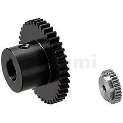 | 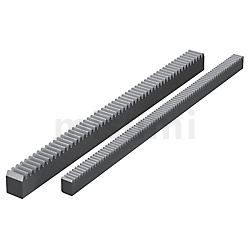 | ||
| Representative Model: C-GEAKBB1.0-36-10-B-15N | Representative Model: GEFHB1.0-30-8-15-W10-H26 | Representative Model: RGEAH1.0-500-A | ||
| Advantages: Nitriding treatment, high cost performance | Advantage: custom size | Advantages: High tooth surface hardness, length can be extended |