Electric Cylinder, Standard Type E-ECTL90

Brand :
MISUMI
Caution
Product Description
An electric cylinder is an electromechanical device used to produce linear motion (a straight-line forward or backward movement). It consists of a ball screw and a piston rod, which is extended and retracted and generates the linear movement, similar to a pneumatic cylinder.
Product Overview
An electric cylinder is a device that converts the rotational motion of an electric motor into linear motion through a ball screw, driving the extension and retraction of the cylinder rod.
Compared with traditional hydraulic and pneumatic cylinder, it has the characteristis of energy saving, space-saving design, low noise, pollution fee and low maintenance cost, achieving the goal of overall cost reduction.
The structure of a MISUMI electric cylinder is composed of an aluminum alloy body, ball screw, and push rod.
The motor mounting hole size and position are processed according to the customer's specified motor brand. A customized motor mounting plate and sensor switches are optional.
Dimensional Drawing
| ■Motor Direction BC(Direct connection) | RC(Parallel connection) | ■Basic Specifications
| |||||||||||||||||||||
 |  |
 Material
 Surface treatment
| E-ECTL90 Stroke S | 50 | 100 | 150 | 200 | 250 | 300 | 350 | 400 | 450 | 500 | 550 | 600 | 650 | 700 | 750 | 800 | 850 | 900 | 950 | 1000 | |
| L | Direct connection | 510 | 560 | 610 | 660 | 710 | 760 | 810 | 860 | 910 | 960 | 1010 | 1060 | 1110 | 1160 | 1210 | 1260 | 1310 | 1360 | 1410 | 1460 |
| Parallel connection | 462 | 512 | 562 | 612 | 662 | 712 | 762 | 812 | 862 | 912 | 962 | 1012 | 1062 | 1112 | 1162 | 1212 | 1262 | 1312 | 1362 | 1412 | |
| Body mass (kg) (Reference) | Direct connection | 12 | 13 | 14 | 15 | 16 | 17 | 18 | 19 | 20 | 21 | 22 | 23 | 24 | 25 | 26 | 27 | 28 | 29 | 30 | 31 |
| Parallel connection | 13 | 14 | 15 | 16 | 17 | 18 | 19 | 20 | 21 | 22 | 23 | 24 | 26 | 27 | 28 | 29 | 30 | 31 | 32 | 33 | |
 When choose GD (Guide mechanism), the total length L is L-21
Specification Table
Please follow the selection steps ~
~ select the model and parameters to order.
※1The maximum speed is a reference value based on the servo motor's maximum speed of 3000 rpm. If the stroke exceeds 300, the speed should be reduced accordingly to avoid resonance.
※2 Motor code M is only applicable to M1000W and M1500W
 The motor bracket type P is compatible with several motor brands. Please refer to the Motor Code and Corresponding Brand table for details.
The motor acceleration and deceleration time should be set to at least 0.2 seconds.
■Recommended servo motor list
■Components
■E-ECTL Sensor specification
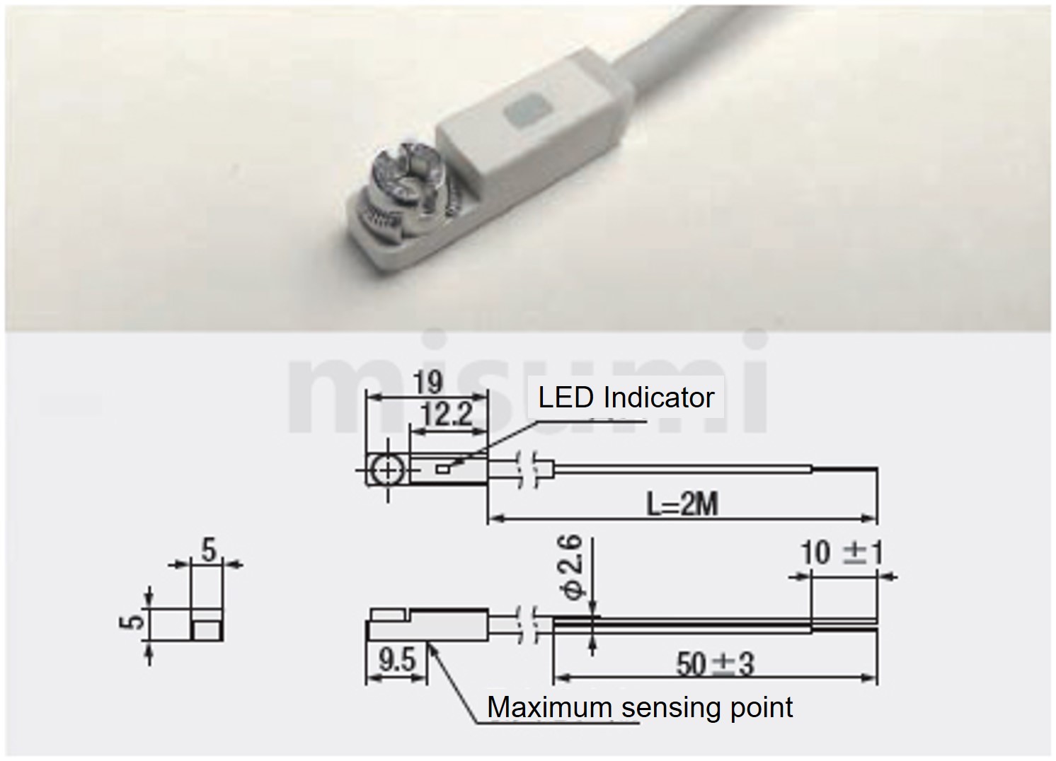
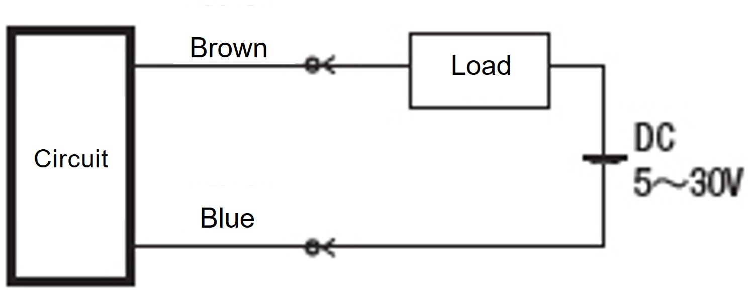
■Sensor wiring diagram
■Sensor parameters
 ~
~ select the model and parameters to order.
 | Type | - |  Lead Lead | - |  Stroke S Stroke S | - |  Motor direction Motor direction | - |  Motor code Motor code | - |  Mounting method Mounting method | - | Number of sensor | |
| E-ECTL90 | - | 10 | - | S1000 | - | RC | - | M1500W | - | HA | - | C3 |
| Model | Stroke S | Motor Drirection | Motor Code | Mounting Method | Number of Sensor | Rated Thrust (N) | Max. Speed (mm/s)※1 | Max. Payload(kg) | Positioning Repeatability(mm) (mm) | Body WidthBall Screw | ||||
| Type | Lead (mm) | 50m incremental | Brand | Power W | Horizontal Use | Vertical Use | ||||||||
| E-ECTL90 | 05 | 50~1000 | BC(Direct connection) RC(Parallel connection) | P(Motor Table) M(Mitsubishi)※2 Z(Customized) | 1000W | NA(Body Mounting) FA(Front Flange) HA(Horizontal) GD(With Guiding Mechanism) | C0(Not provided) C1(1 pc) C2(2 pcs) C3(3 pcs) | 5100 | 166 | 405 | 145 | ±0.02 | □93 | Φ32 (C7) |
| 1500W | 7650 | 608 | 218 | |||||||||||
| 2000W | 10200 | 811 | 291 | |||||||||||
| 10 | 1000W | 2550 | 333 | 202 | 72 | |||||||||
| 1500W | 3825 | 304 | 109 | |||||||||||
| 2000W | 5100 | 405 | 145 | |||||||||||
| 20 | 1000W | 1275 | 666 | 101 | 36 | |||||||||
| 1500W | 1912 | 152 | 54 | |||||||||||
| 2000W | 2550 | 202 | 72 | |||||||||||
※2 Motor code M is only applicable to M1000W and M1500W
The motor bracket type P is compatible with several motor brands. Please refer to the Motor Code and Corresponding Brand table for details.The motor acceleration and deceleration time should be set to at least 0.2 seconds.■Motor Code and Corresponding Brands

| Code | Brand |
| P | Panasonic / Delta / HCFA |
| M | Mitsubishi |
| Z | Customized |

■Motor mounting hole dimension
| Brand | Motor code | With / Without Brake | Power | Voltage | Servo Motor Model | Driver Model |
| Panasonic | P | Without Brake (Horizontal Use) | 50W | 220V | MSMF5AZL1U2M | MADLN05SE |
| With Brake (Vertical Use) | MSMF5AZL1V2M | |||||
| Without Brake (Horizontal Use) | 100W | MSMF012L1U2M | MADLN05SE | |||
| With Brake (Vertical Use) | MSMF012L1V2M | |||||
| Without Brake (Horizontal Use) | 200W | MHMF022L1U2M | MADLN15SE | |||
| With Brake (Vertical Use) | MHMF022L1V2M | |||||
| Without Brake (Horizontal Use) | 400W | MHMF042L1U2M | MBDLN25SE | |||
| With Brake (Vertical Use) | MHMF042L1V2M | |||||
| Without Brake (Horizontal Use) | 750W | MHMF082L1U2M | MCDLN35SE | |||
| With Brake (Vertical Use) | MHMF082L1V2M | |||||
| Without Brake (Horizontal Use) | 1000W | MDMF102L1G6M | MDDLN45SE | |||
| With Brake (Vertical Use) | MDMF102L1H6M | |||||
| Without Brake (Horizontal Use) | 1500W | MDMF152L1G6 | MDDLN55SE | |||
| With Brake (Vertical Use) | MDMF152L1H6 | |||||
| Without Brake (Horizontal Use) | 2000W | MDMF202L1G6 | MEDLN83SE | |||
| With Brake (Vertical Use) | MDMF202L1H6 | |||||
| Mitsubishi | M | Without Brake (Horizontal Use) | 50W | 220V | HG-MR053 | MR-J4-10A |
| With Brake (Vertical Use) | HG-MR053B | |||||
| Without Brake (Horizontal Use) | 100W | HG-KR13 | MR-J4-10A | |||
| With Brake (Vertical Use) | HG-KR13B | |||||
| Without Brake (Horizontal Use) | 200W | HG-KR23 | MR-J4-20A | |||
| With Brake (Vertical Use) | HG-KR23B | |||||
| Without Brake (Horizontal Use) | 400W | HG-KR43 | MR-J4-40A | |||
| With Brake (Vertical Use) | HG-KR43B | |||||
| Without Brake (Horizontal Use) | 750W | HG-KR73 | MR-J4-70A | |||
| With Brake (Vertical Use) | HG-KR73B | |||||
| Without Brake (Horizontal Use) | 1000W | HG-SR102 | MR-J4-100A | |||
| With Brake (Vertical Use) | HG-SR102B | |||||
| Without Brake (Horizontal Use) | 1500W | HG-SR152 | MR-J4-200A | |||
| With Brake (Vertical Use) | HG-SR152B | |||||
| Yaskawa | M | Without Brake (Horizontal Use) | 50W | 220V | SGM7J-01AFC6S | SGD7S-R90A00A002 |
| With Brake (Vertical Use) | SGM7J-01AFC6E | |||||
| Without Brake (Horizontal Use) | 100W | SGM7J-01AFC6S | SGD7S-R90A00A002 | |||
| With Brake (Vertical Use) | SGM7J-01AFC6E | |||||
| Without Brake (Horizontal Use) | 200W | SGM7J-02AFC6S | SGD7S-1R6A00A002 | |||
| With Brake (Vertical Use) | SGM7J-02AFC6E | |||||
| Without Brake (Horizontal Use) | 400W | SGM7J-04AFC6S | SGD7S-2R8A00A002 | |||
| With Brake (Vertical Use) | SGM7J-04AFC6E | |||||
| Without Brake (Horizontal Use) | 750W | SGM7J-08AFC6S | SGD7S-5R5A00B202 | |||
| With Brake (Vertical Use) | SGM7J-08AFC6E | |||||
| Delta | M | Without Brake (Horizontal Use) | 100W | 220V | ECM-B3L-C20401RS1 | ASD-B3-0121-L |
| With Brake (Vertical Use) | ECM-B3L-C20401SS1 | |||||
| Without Brake (Horizontal Use) | 200W | ECM-B3M-C20602RS1 | ASD-B3-0221-L | |||
| With Brake (Vertical Use) | ECM-B3M-C20602SS1 | |||||
| Without Brake (Horizontal Use) | 400W | ECM-B3M-C20604RS1 | ASD-B3-0421-L | |||
| With Brake (Vertical Use) | ECM-B3M-C20604SS1 | |||||
| Without Brake (Horizontal Use) | 750W | ECM-B3M-C20807RS1 | ASD-B3-0721-L | |||
| With Brake (Vertical Use) | ECM-B3M-C20807SS1 | |||||
| P | Without Brake (Horizontal Use) | 1000W | ECM-B3M-E21310RS1 | ASD-B3-0121-L | ||
| With Brake (Vertical Use) | ECM-B3M-E21310SS1 | |||||
| Without Brake (Horizontal Use) | 1500W | ECM-B3M-E21315RS1 | ASD-B3-1521-L | |||
| With Brake (Vertical Use) | ECM-B3M-E21315SS1 | |||||
| Without Brake (Horizontal Use) | 2000W | ECM-B3M-E21320RS1 | ASD-B3-2023-L | |||
| With Brake (Vertical Use) | ECM-B3M-E21320SS1 |
■Components
| Component name | Type | 1000W·1500W·2000W | |||
| Direct connection | Coupling | Clamping type with keyway | Outside diameter | Ball screw side | Motor side |
| Φ55 | Φ22 | Φ22(MitsubishiΦ24) | |||
| Parallel connection | Ball screw pulley | Nickel plated steel | 8M-28Teeth×Φ22 | ||
| Motor pulley | 8M-28Teeth×Φ22(MitsubishiΦ24) | ||||
| Timing belt | Glass fiber core rubber | 480-8M-30 | |||
| Sensor(Optional) | DMST-020-2M (DC 2-wire, Normal open) | ||||
■E-ECTL Sensor specification

■Sensor wiring diagram

■Sensor parameters
| Mode | Output Type | Install Method | Detection Method | Working Voltage | Current Consumption | Output Current | Repeatability | Switching Frequency | Indicator Light | Working Environment Temperature | Cable Length | Protection Rating |
| DMST DMSE | DC 2-wire, Normal open | Screw clamp to cylinder groove | Magnet ring | 5~30V DC | ≦0.05mA | ≦100mA | <0.2㎜ | ≦2000Hz | Red light | -20~+70℃ | 2m | IP67 |
Product Features
■Structure

■Advantages
・Positioning Repeatability ±0.01
・Commonly used for vertical installations and axial thrust applications.
・Suitable for pressing, riveting, clamping, and pushing/pulling mechanisms.
・Can replace pneumatic cylinders for similar functions.

■Advantages
・Positioning Repeatability ±0.01
・Commonly used for vertical installations and axial thrust applications.
・Suitable for pressing, riveting, clamping, and pushing/pulling mechanisms.
・Can replace pneumatic cylinders for similar functions.
| Main body installation | Front flange installation |
 |  |
| Horizontal installation | Installation with guide mechanism |
 |  |
Precautions
■Precautions for use
①Operating environment: Room temperature (-20℃ to 40℃). Avoid corrosive, flammable, electromagnetic, or moist environments.
②Ensure the installation surface is vibration and pressure-resistant, with flatness within ±0.05mm/500mm.
③Use a motor with a brake when the electric cylinder is mounted vertically.
④Protect the cylinder from vibration and impact. Prevent the push rod from rotating and the cylinder from deforming.
Usage Methods
Motor Installation and Timing Belt Adjustment Method
Standard type direct connection_E-ECTL
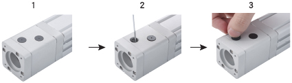
1) Open the plastic hole cover and manually turn the coupling bolt to align with the hole.
2) Use a hex wrench to loosen the coupling bolt, then tighten it after installing the motor.
3) Finally, reinsert the plastic hole cover to complete the motor installation.
Standard type parrallel connection_E-ECTL

1) Remove the motor cover and install the motor. Note that the motor mounting screws don't need to be tightened yet to allow position adjustment.
2) Install the timing pulley on the motor shaft, ensuring it is parallel with the timing pulley on the ball screw.
3) Tighten the timing pulley screw and install the timing belt.
4) Adjust the timing belt tension using the adjusting screw on the body.
5) Use a tension tester to measure the belt tension to ensure it matches the reference value (see the table below).
6) Finally, tighten the motor mounting screws and re-install the motor cover to complete the installation.
Electric cylinder belt tension value (reference)
| Motor Power (W) | Electric Cylinder Model | Timing belt type | Belt width (mm) | Belt center distance (mm) | Belt thickness (mm) | Tension value N (reference) |
| 100W | E-ECTL40/E-ECRL5 | 2GT | 12 | 55 | 1.3 | 12~17 |
| 200W | E-ECTL50/E-ECRL8 | 3GT | 15 | 81 | 2.5 | 32~42 |
| 400W | E-ECTL60/E-ECRL8 | |||||
| E-ECTLT60 | 5GT | 75 | 4 | 60~75 | ||
| 750W | E-ECTL75/E-ECRL10 | 107 | ||||
| E-ECTLT75 | 8YU | 25 | 104 | 5.2 | 125~155 | |
| 1000W | E-ECTL90/E-ECTLT90 | 8M | 30 | 128 | 6.1 | 409~450 |
| 1500W | ||||||
| 2000W | E-ECTL90 | |||||
| E-ECTLT110 | 50 | 160 | 573~630 |
Example of Use
■Standard Electric Cylinder usage examples
Application: Transfer mechanism
・Utilize the telescopic function of the vertically mounted electric cylinder to pick and place workpieces on conveyors at different heights.
・Adopt the transplanting mechanism of the electric cylinder, ensuring stable and fast lifting to avoid damage to workpieces during pick-and-place operations.

Related documents
■Regular Lubrication Method
・The Electric Cylinder requires regular lubrication. Initially, add grease after 300 hours of operation. Subsequently, lubricate every 2000 hours.
・Use general lithium-based grease No. 3 (GB7324-1994). Mobil lithium grease EP3 is recommended.
・Use a grease gun for lubrication. Do not use liquid lubricants.
Standard type

1)Remove the silencer and apply grease to the ball screw.
2)Manually extend the push rod several times to ensure the entire screw is lubricated.
※Note: Standard E-ECTL75 and above, along with high-thrust models, include grease nipples for bearing lubrication.
Related Products
| Single Axis Robots, Guide Built in Type | Single Axis Actuators KS series | Electric Cylinder, Radial type | ||
 |  |  | ||
| Representative Part number : E-MGT5-L10-100-BC-P10-C | Representative Part number : C-KS4001-B1-100-F1-W2 | Representative Part number : E-ECRL5-05-S100-BC-P100W |
Application Industry
| Electronic | Smartphone | Lithium battery | ||
 |  |  | ||
| Automotive | Robotics | Medical | ||
 |  |  |