Linear Guide Short Block-Low Profile EG Type (ROHS Compliant)

Brand :
MISUMI
Caution
- **RoHS Compliant Type
Product Description
Linear Guides Short Blocks-Low Profile
These linear guides or linear slides are an economy item, The price is cheaper than the MISUMI standard product.They offer a wide variety of sizes to choose from.
[Feature]
● Rail Length Minimum/Maximum (mm.): 100 and 1980(3960)
● Assembly Height (mm.): 24, 28, 33, 42,
● Block Type : Short Block Low Profile
● Option: Set (Rail + Block) / Block only
● Material: Carbon Steel 56HRC
[Application]
It is used in a variety of machines such as CNC machines, 3D printers, measuring instruments, and so on.
Product Overview
Linear guides, also known as slide rails, linear guideways, or linear slides, are used for linear reciprocating motion. For the same component volume, they offer higher rated loads and linear motion precision than linear bushings. They can also withstand certain torque loads and achieve high-precision linear motion under high-load conditions.
Linear guides are used to support and guide moving parts to perform reciprocating linear motion in a given direction. They are primarily used in mechanical structures requiring high precision. Rolling steel balls are used between the moving and fixed elements of the linear guide instead of an intermediate medium.
Linear guides are used to support and guide moving parts to perform reciprocating linear motion in a given direction. They are primarily used in mechanical structures requiring high precision. Rolling steel balls are used between the moving and fixed elements of the linear guide instead of an intermediate medium.
Product Features
Feature 1: Standard rails are equipped with dust covers to prevent dirt from accumulating in the mounting holes when the equipment is in use.
Feature 2: The slide rail and block contact via rolling balls, resulting in minimal shaking, making them suitable for equipment requiring high precision.
Feature 3: Due to point-to-surface contact, frictional resistance is very low, allowing for subtle movements and precise positioning of the device.
Feature 4: Because the balls have their own rolling grooves, the force on the rotating surface is dispersed, resulting in a large allowable load capacity.
Feature 5: Linear guides do not easily generate frictional heat during operation and are resistant to thermal deformation, making them suitable for high-speed motion.
Feature 2: The slide rail and block contact via rolling balls, resulting in minimal shaking, making them suitable for equipment requiring high precision.
Feature 3: Due to point-to-surface contact, frictional resistance is very low, allowing for subtle movements and precise positioning of the device.
Feature 4: Because the balls have their own rolling grooves, the force on the rotating surface is dispersed, resulting in a large allowable load capacity.
Feature 5: Linear guides do not easily generate frictional heat during operation and are resistant to thermal deformation, making them suitable for high-speed motion.
Dimensional Drawing
E-ELGH15、20、30SA

E-ELGH25SA
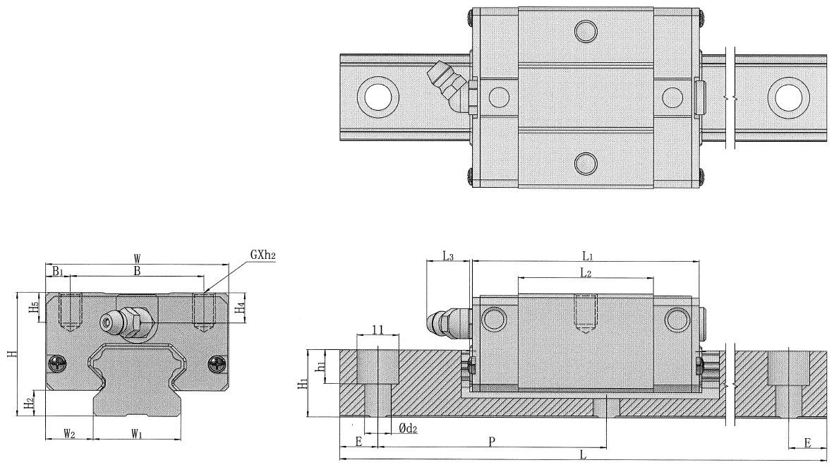
 Dimensional tolerance for length L is: ±2mmSince this product has no surface treatment, please be sure to take anti-rust measures.
Specifications Table
■ Assembly Set
| Part Number |  Length L Length L(1mm increments) | Block Dimensions (mm) | Guide Rail Dimension (mm) | |||||||||||||||||||
 Type Type |  Nominal Model Nominal Model | W | B | B1 | L1 | L2 | G×h2 | L3 | H4 | H5 | W1 | W2 | H | H2 | Counterbored Hole | P | H1 | E | Rail fixing bolts | |||
| d2×d1×h1 | ||||||||||||||||||||||
| E-ELGH*SA | 15 | 100~3960 | 34 | 26 | 4 | 41.1 | 23.1 | M4×6 | 5.3 | 5.5 | 6 | 15 | 9.5 | 24 | 4.5 | 4.5×7.5×4.5 | 60 | 12.5 | Please refer to L specified Dimension Calculation Table | M4×16 | ||
| 20 | 42 | 32 | 5 | 50.2 | 29 | M5×7 | 12.5 | 6 | 7.5 | 20 | 11 | 28 | 6 | 6×9.5×8.5 | 15.5 | M5×16 | ||||||
| 25 | 48 | 35 | 6.5 | 59.5 | 35.5 | M6×9 | 12 | 8 | 8 | 23 | 12.5 | 33 | 7 | 7×11×9 | 18 | M6×20 | ||||||
| 30 | 200~3960 | 60 | 40 | 10 | 71.5 | 41.5 | M8×12 | 11.5 | 8 | 9 | 28 | 16 | 42 | 10 | 7×11×9 | 80 | 23 | M6×25 | ||||
■ Single Block
| Part Number | Block Dimensions (mm) | |||||||||
| Type | Nominal Model | W | B | B1 | L1 | L2 | G×h2 | L3 | H4 | H5 |
| E-ELGH*SAB | 15 | 34 | 26 | 4 | 41.1 | 23.1 | M4×6 | 5.3 | 5.5 | 6 |
| 20 | 42 | 32 | 5 | 50.2 | 29 | M5×7 | 12.5 | 6 | 7.5 | |
| 25 | 48 | 35 | 6.5 | 59.5 | 35.5 | M6×9 | 12 | 8 | 8 | |
| 30 | 60 | 40 | 10 | 71.5 | 41.5 | M8×12 | 11.5 | 8 | 9 | |
■ Detailed Dimensions of L-Dimension Specified Type
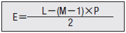
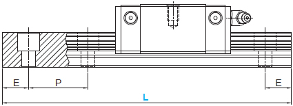
The L-dimension specified type is cut equally at both ends of the rail. Please refer to the table below for the number of rail mounting holes (M).
Additionally, the calculation formula for dimension E is as follows:
| Nominal Model | 15 | 20 | 25 | 30 | Number of Mounting Holes M |
| L | 100~131 | 100~139 | 100~141 | - | 2 |
| 132~191 | 140~199 | 142~201 | 200~279 | 3 | |
| 192~251 | 200~259 | 202~261 | 280~343 | 4 | |
| 252~311 | 260~319 | 262~321 | 344~423 | 5 | |
| 312~371 | 320~379 | 322~381 | 424~503 | 6 | |
| 372~431 | 380~439 | 382~441 | 504~583 | 7 | |
| 432~491 | 440~499 | 442~501 | 584~663 | 8 | |
| 492~551 | 500~559 | 502~561 | 664~743 | 9 | |
| 552~611 | 560~619 | 562~621 | 744~823 | 10 | |
| 612~671 | 620~679 | 622~681 | 824~903 | 11 | |
| 672~731 | 680~739 | 682~741 | 904~983 | 12 | |
| 732~791 | 740~799 | 742~801 | 984~1063 | 13 | |
| 792~851 | 800~859 | 802~861 | 1064~1143 | 14 | |
| 852~911 | 860~919 | 862~921 | 1144~1223 | 15 | |
| 912~971 | 920~979 | 922~981 | 1224~1303 | 16 | |
| 972~1031 | 980~1039 | 982~1041 | 1304~1383 | 17 | |
| 1032~1091 | 1040~1099 | 1042~1101 | 1384~1463 | 18 | |
| 1092~1151 | 1100~1159 | 1102~1161 | 1464~1543 | 19 | |
| 1152~1211 | 1160~1219 | 1162~1221 | 1544~1623 | 20 | |
| 1212~1271 | 1220~1279 | 1222~1281 | 1624~1703 | 21 | |
| 1272~1331 | 1280~1339 | 1282~1341 | 1704~1783 | 22 | |
| 1332~1391 | 1340~1399 | 1342~1401 | 1784~1863 | 23 | |
| 1392~1451 | 1400~1459 | 1402~1461 | 1864~1943 | 24 | |
| 1452~1511 | 1460~1519 | 1462~1521 | 1944~2023 | 25 | |
| 1512~1571 | 1520~1579 | 1522~1581 | 2024~2103 | 26 | |
| 1572~1631 | 1580~1639 | 1582~1641 | 2104~2183 | 27 | |
| 1632~1691 | 1640~1699 | 1642~1701 | 2184~2263 | 28 | |
| 1692~1751 | 1700~1759 | 1702~1761 | 2264~2343 | 29 | |
| 1752~1811 | 1760~1819 | 1762~1821 | 2344~2423 | 30 | |
| 1812~1871 | 1820~1879 | 1822~1881 | 2424~2503 | 31 | |
| 1872~1931 | 1880~1939 | 1882~1941 | 2504~2583 | 32 | |
| 1932~1991 | 1940~1999 | 1942~2001 | 2584~2663 | 33 | |
| 1992~2051 | 2000~2059 | 2002~2061 | 2664~2743 | 34 | |
| P | 60 | 80 | |||
| Nominal Model | 15 | 20 | 25 | 30 | Number of Mounting Holes M |
| L | 2052~2111 | 2060~2119 | 2062~2121 | 2744~2823 | 35 |
| 2112~2171 | 2120~2179 | 2122~2181 | 2824~2903 | 36 | |
| 2172~2231 | 2180~2239 | 2182~2241 | 2904~2983 | 37 | |
| 2232~2291 | 2240~2299 | 2242~2301 | 2984~3063 | 38 | |
| 2292~2351 | 2300~2359 | 2302~2361 | 3064~3143 | 39 | |
| 2352~2411 | 2360~2419 | 2362~2421 | 3144~3223 | 40 | |
| 2412~2471 | 2420~2479 | 2422~2481 | 3224~3303 | 41 | |
| 2472~2531 | 2480~2539 | 2482~2541 | 3304~3383 | 42 | |
| 2532~2591 | 2540~2599 | 2542~2601 | 3384~3463 | 43 | |
| 2592~2651 | 2600~2659 | 2602~2661 | 3464~3543 | 44 | |
| 2652~2711 | 2660~2719 | 2662~2721 | 3544~3623 | 45 | |
| 2712~2771 | 2720~2779 | 2722~2781 | 3624~3703 | 46 | |
| 2772~2831 | 2780~2839 | 2782~2841 | 3704~3783 | 47 | |
| 2832~2891 | 2840~2899 | 2842~2901 | 3784~3863 | 48 | |
| 2892~2951 | 2900~2959 | 2902~2961 | 3864~3943 | 49 | |
| 2952~3011 | 2960~3019 | 2962~3021 | 3944~3960 | 50 | |
| 3012~3071 | 3020~3079 | 3022~3081 | - | 51 | |
| 3072~3131 | 3080~3139 | 3082~3141 | 52 | ||
| 3132~3191 | 3140~3199 | 3142~3201 | 53 | ||
| 3192~3251 | 3200~3259 | 3202~3261 | 54 | ||
| 3252~3311 | 3260~3319 | 3262~3321 | 55 | ||
| 3312~3371 | 3320~3379 | 3322~3381 | 56 | ||
| 3372~3431 | 3380~3439 | 3382~3441 | 57 | ||
| 3432~3491 | 3440~3499 | 3442~3501 | 58 | ||
| 3492~3551 | 3500~3559 | 3502~3561 | 59 | ||
| 3552~3611 | 3560~3619 | 3562~3621 | 60 | ||
| 3612~3671 | 3620~3679 | 3622~3681 | 61 | ||
| 3672~3731 | 3680~3739 | 3682~3741 | 62 | ||
| 3732~3791 | 3740~3799 | 3742~3801 | 63 | ||
| 3792~3851 | 3800~3859 | 3802~3861 | 64 | ||
| 3852~3911 | 3860~3919 | 3862~3921 | 65 | ||
| 3912~3960 | 3920~3960 | 3922~3960 | 66 | ||
| P | 60 | 80 | |||
Material Specification
| Type | Assembly Set / Single Item | [ M ] Material | [ H ] Hardness |
| E-ELGH*SA | Assembly Set | Carbon Steel | 58HRC~ |
| E-ELGH*SAB | Single Block |
| Rail Nominal Size | Grease Nipple Thread Nominal * Pitch * Thread Length | Grease Nipple Material |
| 15 | M4*0.7*5 | Brass |
| 20 | M6*1*6 | |
| 25 | ||
| 30 |
Alterations
| Alterations |  Code Code | Spec. |
| 2-Block Specification | B2 | 1 block added to singe-block product to ship as 2-block item. If the rail is too short to accommodate multiple blocks, the blocks will be packaged and shipped separately. If the rail is too short to accommodate multiple blocks, the blocks will be packaged and shipped separately. |
| 3-Block Specification | B3 | 2 blocks added to 1-block product to ship as 3 blocks item.If the rail is too short to accommodate multiple blocks, the blocks will be packaged and shipped separately. |
| 4-Block Specification | B4 | Three additional blocks are added to the single-block product and shipped as a 4-block assembly.If the rail is too short to accommodate multiple blocks, the blocks will be packaged and shipped separately. |
Dual-axis Parallel Use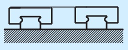 | W2 | Set the height H matching tolerance of the 2 rails within 0.02mm. Width W of the 2 rails2Matching tolerance within 0.02~0.03mm. Please be sure to order in actual quantities (even numbers). |
| Preload Adjustment | ZA:Light Preload | Change Z0 (No Clearance) type to ZA (Light Preload) type. |
| ZB:Medium Preload | Change Z0 (No Clearance) type to ZB (Medium Preload) type. | |
| Low Temperature Black Chrome Plating (Rail) | R | Rail surface treatment with low temperature black chrome plating. |
| Rail Ends Cut | Left End Cut ES | Specify the end distance in 0.5mm increments. If the specified end distance is greater than or close to the hole pitch, cutting may result in a broken hole. If only one side is specified, the other side will be cut based on the remaining length of the total length.EB+ES=2E If cutting is not possible, it will be processed by standard equal division |
| Right End Cut EB |
Accuracy Standards
Unit: mm
| Dimensional Accuracy Type | Accuracy Standards | 15,20,25,30,35 | 45,55,65 |
| Linear Guides- High・Low Profile | Dimensional Tolerance of Height H | ±0.1 | ±0.1 |
| Width W2dimensional tolerance | ±0.1 | ±0.1 | |
| Height H Pair Variation | 0.02 | 0.03 | |
| Width W2pair variation | 0.02 | 0.03 |
● Running Parallelism
| Rail Length (mm) | Accuracy Grade (μm) |
| 100-200 | 19 |
| 200-300 | 21 |
| 300-500 | 23 |
| 500-700 | 28 |
| 700-900 | 30 |
| 900-1100 | 33 |
| 1100-1500 | 36 |
| 1500-1900 | 39 |
| 1900-2500 | 43 |
| 2500-3100 | 46 |
| 3100-3600 | 50 |
| 3600-3960 | 52 |
Allowable Load
| Nominal Model | Basic Load Rating | Static Allowable Moment | Weight | |||
| C (Dynamic) kN | Co (Static) kN | MA・MB kN-m | MC kN-m | Block (kg) | Guide Rail kg/m | |
| 15 | 5.35 | 9.40 | 0.04 | 0.08 | 0.09 | 1.25 |
| 20 | 7.23 | 12.74 | 0.06 | 0.13 | 0.15 | 2.08 |
| 25 | 11.4 | 19.50 | 0.12 | 0.23 | 0.25 | 2.6 |
| 30 | 16.42 | 28.10 | 0.21 | 0.4 | 0.45 | 4.35 |

Selection Calculation
The service life of a linear guide is divided into:
① Running Distance Life here
here
① Running Distance Life
When a linear guide undergoes linear reciprocating motion under load, repeated stress acts on the rolling elements (steel balls) or rolling surfaces (rails), resulting in scale-like damage known as material fatigue flaking. The total travel distance before this initial flaking occurs is called the service life of the linear guide.
② Rated LifeRated life refers to the total travel distance reached by 90% of a group of identical linear guides moving under the same conditions without flaking. The rated life can be calculated using the basic dynamic load rating and the load applied to the linear guide according to the following formula.
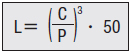
When actually using linear guides, load calculation should be performed first. It is not easy to calculate the load in linear reciprocating motion because vibration or impact exists during movement, and the distribution of vibration or impact relative to the linear guide must be fully considered. Additionally, operating temperature also significantly affects service life. Incorporating these conditions, the above calculation formula becomes the following.
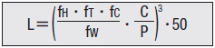
③ Service Life in HoursWhen actually using linear guides, load calculation should be performed first. It is not easy to calculate the load in linear reciprocating motion because vibration or impact exists during movement, and the distribution of vibration or impact relative to the linear guide must be fully considered. Additionally, operating temperature also significantly affects service life. Incorporating these conditions, the above calculation formula becomes the following.
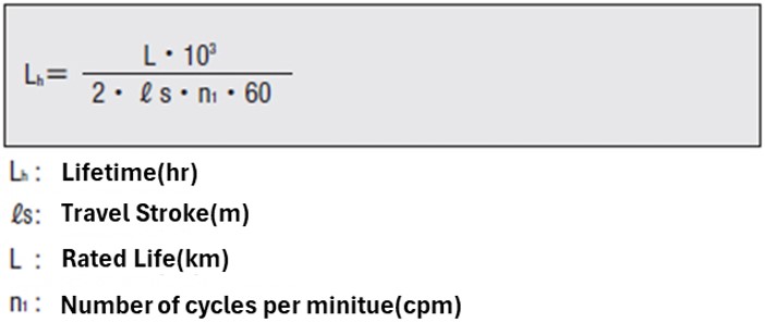
The service life can be calculated by determining the travel distance per unit of time. When the stroke length and number of cycles are constant, it can be calculated using the following formula.
For specific life and load calculation methods, click
 here
hereUsage Method
Installation Method for Medium and Heavy Load Linear Guides
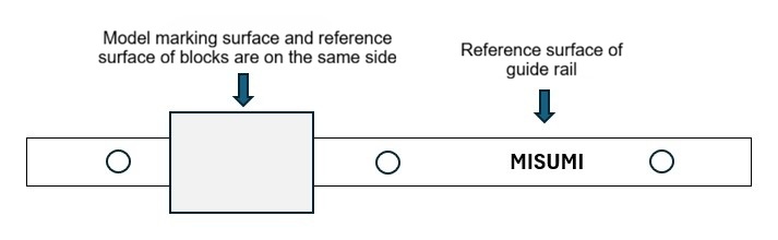
The blocks of MISUMI economy type medium and heavy load linear guides are provided with a datum plane (see the figure below).
When installing the linear guide, please align this datum plane correctly with the mounting datum planes of the table and the base, then secure it.
Rust Prevention Note: When selecting carbon steel products, please perform appropriate rust prevention treatment throughout the entire process of unpacking, installation, and use, according to the actual operating environment.
Please note: Purchasing a block separately may result in changes to the preload.
■ About Use
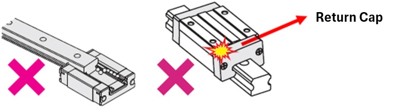
① MISUMI linear guides are equipped with retainers. Although the steel balls do not easily fall out when removing the block, they may fall out if the block is removed from the rail at high speed or inserted into the rail at an angle. Please handle the assembly and disassembly of the block with care.
② Be sure to avoid impacting the return caps of the ball circulation path, as this will affect the circulation of the steel balls and cause poor sliding performance.
③ If rust prevention is required, please prioritize products with low-temperature black chrome plating surface treatment or stainless steel SUS440C series materials.
■ Regarding Maintenance (Grease Supply)
① Grease forms an oil film on the surfaces of the steel balls and the raceway of the linear guide, effectively reducing friction and preventing seizing.
A reduction or aging of grease will significantly impact the service life of the linear guide; therefore, please replenish grease at appropriate times according to the operating conditions.
MISUMI linear guides are pre-lubricated with grease at the factory and can be used immediately.
② Recommended Greasing Intervals:
The blocks of MISUMI economy type medium and heavy load linear guides are provided with a datum plane (see the figure below).
When installing the linear guide, please align this datum plane correctly with the mounting datum planes of the table and the base, then secure it.
Rust Prevention Note: When selecting carbon steel products, please perform appropriate rust prevention treatment throughout the entire process of unpacking, installation, and use, according to the actual operating environment.
Please note: Purchasing a block separately may result in changes to the preload.
■ About Use
① MISUMI linear guides are equipped with retainers. Although the steel balls do not easily fall out when removing the block, they may fall out if the block is removed from the rail at high speed or inserted into the rail at an angle. Please handle the assembly and disassembly of the block with care.
② Be sure to avoid impacting the return caps of the ball circulation path, as this will affect the circulation of the steel balls and cause poor sliding performance.
③ If rust prevention is required, please prioritize products with low-temperature black chrome plating surface treatment or stainless steel SUS440C series materials.
■ Regarding Maintenance (Grease Supply)
① Grease forms an oil film on the surfaces of the steel balls and the raceway of the linear guide, effectively reducing friction and preventing seizing.
A reduction or aging of grease will significantly impact the service life of the linear guide; therefore, please replenish grease at appropriate times according to the operating conditions.
MISUMI linear guides are pre-lubricated with grease at the factory and can be used immediately.
② Recommended Greasing Intervals:
Generally, perform grease maintenance every 3 months.
Please adjust the specific maintenance timing based on actual conditions; it is recommended to check the grease condition every 100km.
*The above are grease replenishment intervals based on travel distance standards. Depending on the operating environment, if the grease ages or becomes heavily contaminated, the replenishment interval must be appropriately shortened.
Please adjust the specific maintenance timing based on actual conditions; it is recommended to check the grease condition every 100km.
*The above are grease replenishment intervals based on travel distance standards. Depending on the operating environment, if the grease ages or becomes heavily contaminated, the replenishment interval must be appropriately shortened.
Precautions
For proper use, the installation of linear guides must satisfy the following four points:
① Check if the mounting surface shape causes interference.
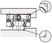
② Maintain the flatness of the workpiece mounting surface within approximately 5μ; otherwise, the block may undergo slight deformation.
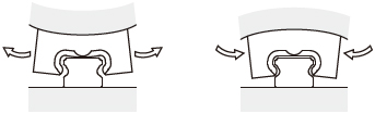
③ Check if the rail parallelism and mating height error values are within the allowable installation tolerances.


④ Use standardized installation methods.

Click here for detailed installation methods.here
② Maintain the flatness of the workpiece mounting surface within approximately 5μ; otherwise, the block may undergo slight deformation.
③ Check if the rail parallelism and mating height error values are within the allowable installation tolerances.


④ Use standardized installation methods.

Click here for detailed installation methods.
hereExample of Use

Mechanism Name: Belt-Driven Handling Device
Feature 1: Suitable for medium-precision, medium-frequency driving and positioning.
Feature 2: Achieves miniaturization by configuring a single linear guide in the center.
For more information, clickhere
Feature 1: Suitable for medium-precision, medium-frequency driving and positioning.
Feature 2: Achieves miniaturization by configuring a single linear guide in the center.
For more information, click
hereApplication Industries
| Medical | Smartphones | |
 |  | |
| Robotics | Electronics and Electrical Appliances | |
 |  |
Related Products
| Miniature Linear Guides - Standard Light Preload Type | Miniature Linear Guides - Wide Slide Rail Type | Heavy Load Linear Guides | ||
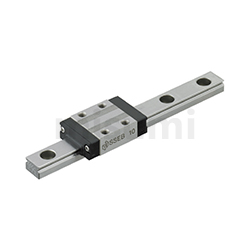 | 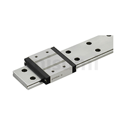 | 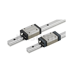 | ||
| Representative Models:SSEB10-55 | Representative Models:SSEBW12-200 | Representative Models:SXR24-280 |
Related Documents
Please refer to the installation and usage methods for linear guideshere
here