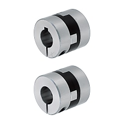
Oldham Couplings - Large Shaft Diameter, Set Screw / Clamping / Spacers, Economy series
Brand :
MISUMI
Caution
Product Description
Only part numbers that can be generated via the filter(Configurator bar on the left) are currently available.
Part numbers generated using the configuration bar on the left side of the page are valid.
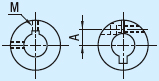
Drawing

 Operating Temperature: -20°C ~ 80°C ETolerances for d1 and d2 are values before slit machining.The lateral, angular, and axial misalignment values shown are for each occurring individually.When multiple misalignments are occurring simultaneously, the allowable maximum value of each will be reduced to 1/2.
Material
| Shape | Keywayed Bore |  Material Material |  Accesories Accesories | |||
| d1(One Side) | d2(One Side) | d1・d2(Both Side) | Hub | Spacers | ||
| Set Screw | - | - | EA-MFJWK | Aluminum Alloy | Polyacetal | Set Screw |
| Clamping | EA-MFJCLK | EA-MFJCRK | EA-MFJCWK | Hex Socket Head Cap Screw | ||
Specification
| Part Number | - | Shaft Bore Dia. d1 | - | Shaft Bore Dia. d2 | ||
| - | 16 | - | 20 | ||
| EA-MFJCWK70 | - | 22 | - | 35 |
| Part Number | d1,d2 Selection (However d1≤d2) | d3 | L | ℓ | F | A | Set Screw/ Clamping Screw | |||||||||||||
| Type | D | M | Tightening Torque (N・m) | |||||||||||||||||
| Set Screw EA-MFJWK | 44 | 14 | 15 | 16 | 18 | 20 | 22 | 22.5 | 46 | 15 | 7.5 | - | M 6 | 7.0 | ||||||
| 55 | 18 | 20 | 22 | 25 | 26 | 28 | 57 | 19 | 9.5 | - | M 8 | 15.0 | ||||||||
| 70 | 22 | 25 | 28 | 30 | 35 | 38 | 39 | 77 | 25 | 12.5 | - | M10 | 30.0 | |||||||
| Clamping EA-MFJC EA-MFJCLK EA-MFJCRK EA-MFJCWK | 44 | 14 | 15 | 16 | 18 | 20 | 22.5 | 46 | 15 | 7.5 | 14.5 | M5 | *8.4 | |||||||
| 55 | 18 | 20 | 22 | 25 | 28 | 57 | 19 | 9.5 | 17 | M6 | *14.4 | |||||||||
| 70 | 22 | 25 | 28 | 30 | 35 | 39 | 77 | 25 | 12.5 | 24 | M8 | *30.0 | ||||||||
 *When the shaft diameter is small, clamp screw tightening torque should be higher than the prescribed value to prevent shaft slipping. The above tightening torque is for referenceOnly part numbers that can be generated via the filter(Configurator bar on the left) are currently available.
| Part Number | Allowable Torque (N・m) | Angular Misalignment (°) | Lateral Misalignment (mm) | Static Torsional Spring Constant (N・m/rad) | Max. Rotational Speed (r/min) | Moment of Inertia (kg・m2) | Allowable Axial Misaligntment (mm) | Mass (g) | ||
| Type | D | Set Screw | Clamping | |||||||
| Clamping EA-MFJC EA-MFJCLK EA-MFJCRK EA-MFJCWK | 44 | 30 | 26 | 2 | 1 | 1500 | 12000 | 4 ×10⁻⁵ | ±0.5 | 140 |
| 55 | 45 | 40 | 1.5 | 2800 | 10000 | 11 ×10-5 | ±0.6 | 260 | ||
| 70 | 80 | 72 | 2 | 4800 | 8000 | 40 ×10-5 | ±0.8 | 450 | ||
The allowable torque varies depending on temperature.Alterations

| Alterations | Shaft Bore Dia. | Keyway Width | Keyway | |||||||||||||||||||||||||||
| Spec. | 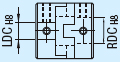 0.1mm increment Ordering Code LDC19.5 RDC21
Values in()are for Clamping Type. | Keyway Width(b) is changed as the table below. Ordering Code KLH8 KRH8 
 Cannot be combined with shaft bore change(LDC·RDC)alteration.Applicable to Keywayed Bore only. Cannot be combined with shaft bore change(LDC·RDC)alteration.Applicable to Keywayed Bore only. | ||||||||||||||||||||||||||||
| Code | LDC(Left Shaft) | RDC(Right Shaft) | KLH(Left Shaft) | KRH(Right Shaft) | LK(Left Shaft) | RK(Right Shaft) | ||||||||||||||||||||||||