Series DC 3-wire proximity sensor

Brand :
MISUMI
Caution
Product Description
Product overview
A proximity switch is a type of position switch that can be operated without mechanical direct contact with the moving part. When an object approaches the induction surface of the switch to the operating distance, the switch can operate without mechanical contact or applying any pressure, thereby driving a DC electrical appliance or providing control commands to a computer (plc) device. A proximity switch is a type of switch-type sensor (that is, a contactless switch). It has the characteristics of both a travel switch and a microswitch, while also providing sensing performance. It operates reliably, has stable performance, fast frequency response, long life, strong anti-interference ability, and features such as being waterproof, shockproof, and corrosion resistant.


Dimensional drawing
| M8 short/medium distance shielded type | M8 short/medium distance unshielded type |
 |  |
| M12 short/medium distance shielded type | M12 short/medium distance unshielded type |
 |  |
| M18 short/medium distance shielded type | M18 short/medium distance unshielded type |
 |  |
| M8 connector type short/medium distance shielded type | M8 connector type short/medium distance unshielded type |
 |  |
| M12 connector type medium distance unshielded | |
 |
 |  |  |
| M8 | M12 | M18 |
Specification table
DC 3-wire type shielded (short distance type)| Dimension | Case size | Detection distance | Connection method | Response time | Model | |
| NPN.NO output | PNP.NO output | |||||
| M8×1.0 | 30 mm | 1.5 mm | 2 m oil resistance reinforced PVC cable | 2000 Hz | C-C08-N01 | C-C08-P01 |
| 45 mm | M8 (3-pin) connector | C-C08-N01-3 | C-C08-P01-3 | |||
| M12 × 1.0 | 35 mm | 2 mm | 2 m oil resistance reinforced PVC cable | C-C12-N01 | C-C12-P01 | |
| M18×1.0 | 5 mm | 1000 Hz | E-MSMX5C118 | E-MSMX5B1D18 | ||
DC 3-wire type shielded (medium distance type)
| Dimension | Case size | Detection distance | Connection method | Response time | Model | |
| NPN.NO output | PNP.NO output | |||||
| M8×1.0 | 30 mm | 2 mm | 2 m oil resistance reinforced PVC cable | 2000 Hz | C-2C08-N01 | C-2C08-P01 |
| 45 mm | M8 (3-pin) connector | C-2C08-N01-3 | C-2C08-P01-3 | |||
| M12 × 1.0 | 35 mm | 4 mm | 2 m oil resistance reinforced PVC cable | 1000 Hz | C-2C12-N01 | C-2C12-P01 |
| M18×1.0 | 8 mm | 500 Hz | E-MSMX8C118 | E-MSMX8B1D18 | ||
DC 3-wire type unshielded (medium distance type)
| Dimension | Case size | Detection distance | Connection method | Response time | Model | |
| NPN.NO output | PNP.NO output | |||||
| M8×1.0 | 30 mm | 4 mm | 2 m oil resistance reinforced PVC cable | 1000 Hz | C-2C08-N11 | C-2C08-P11 |
| 47 mm | M8 (3-pin) connector | C-2C08-N11-3 | C-2C08-P11-3 | |||
| M12 × 1.0 | 35 mm | 8 mm | 2 m oil resistance reinforced PVC cable | 500 Hz | C-2C12-N11 | C-2C12-P11 |
| 50 mm | M12 (four-pin) connector | C-2C12-N11-4 | C-2C12-P11-4 | |||
| M18×1.0 | 45 mm | 16 mm | 2 m oil resistance reinforced PVC cable | 150 Hz | E-MSMX16MC118 | E-MSMX16MB1D18 |
· Input/output circuit diagram
DC 3-wire type NPN output

ZD: Surge absorption Zener diode
Tr: NPN output transistor
D: Power supply reverse connection protection diode

ZD: Surge absorption Zener diode
Tr: NPN output transistor
D: Power supply reverse connection protection diode
DC 3-wire type PNP output

ZD: Surge absorption Zener diode
Tr: PNP output transistor
D: Power supply reverse connection protection diode

ZD: Surge absorption Zener diode
Tr: PNP output transistor
D: Power supply reverse connection protection diode
Specification table (short type/medium)
| Type | Short distance | Medium distance (shielded) | Medium distance (non-shielded) | ||||||
| Dimension | M8 | M12 | M18 | M8 | M12 | M18 | M8 | M12 | M18 |
| Detection distance | 1.5 mm +/-10% | 2 mm +/-10% | 5 mm +/-10% | 2 mm +/-10% | 4 mm +/-10% | 8 mm +/-10% | 4 mm +/-10% | 8 mm +/-10% | 16 mm+/-10% |
| Configuration distance | 0 to 1.2 mm | 0 to 1.6 mm | 0 to 4 mm | 0 to 1.6 mm | 0 to 3.2 mm | 0 to 6.4 mm | 0 to 3.2 mm | 0 to 6.4 mm | 0 to 12.8 mm |
| Hysteresis | 10% or less of the detection distance | 15% or less of the detection distance | |||||||
| Detectable objects | Magnetic metal (for non-magnetic metal, please refer to the characteristic comparison chart) | ||||||||
| Standard detection object | Iron: 8×8×1 mm | Iron: 12×12×1 mm | Iron: 18×18×1 mm | Iron: 8×8×1 mm | Iron: 12×12×1 mm | Iron: 24×24×1 mm | Iron: 12×12×1 mm | Iron: 24×24×1 mm | Iron: 48×48×1 mm |
| Responsive frequency | 2000 Hz | 2000 Hz | 1000 Hz | 2000 Hz | 1000 Hz | 500 Hz | 1000 Hz | 500 Hz | 150 Hz |
| Power voltage | DC 10–30 V, including ripple (p-p) 10% | ||||||||
| Current consumption | 16 mA or less | ||||||||
| Output type | NPN.NO, PNP.NO | ||||||||
| Switch capacity | DC10 to 30 V, 200 mA or less (when -40 to +70℃) | DC10 to 30 V, 200 mA or less | DC10 to 30 V, 200 mA or less (when -40 to +70℃) | DC10 to 30 V, 200 mA or less | DC10 to 30 V, 200 mA or less (when -40 to +70℃) | DC10 to 30 V, 200 mA or less | |||
| Residual pressure | 2 V or less (when load current is 200 mA and lead wire length is 2 m) | 2 V or less (when load current is 200 mA and lead wire length is 2 m) | 2 V or less (when load current is 200 mA and lead wire length is 2 m) | 2 V or less (when load current is 200 mA and lead wire length is 2 m) | 2 V or less (when load current is 200 mA and lead wire length is 2 m) | 2 V or less (when load current is 200 mA and lead wire length is 2 m) | |||
| Indicator | Operation indicator (green/on) | ||||||||
| Protection circuit | Power supply reverse connection protection, surge absorption, load short circuit protection, output reverse connection protection | ||||||||
| Ambient temperature range | During operation and storage: -40 to +85℃ (no freezing, no condensation) | ||||||||
| Ambient humidity range | During operation and storage: 35 to 95%RH (no condensation) | ||||||||
| Temperature influence | Within the temperature range of -40 to +85℃, at +23℃, within +/-15% of the detection distance | ||||||||
| Voltage influence | Within +/-15% of the rated power voltage, at the rated power voltage, within +/-1% of the detection distance | ||||||||
| Insulation resistance | 50 MΩ or more (500 V DC megohmmeter) between the entire charging part and the case | ||||||||
| Withstand voltage | AC 1,000 V 50/60 Hz 1 min Between the charged section and the case | ||||||||
| Vibration (durability) | 10–55 Hz double amplitude 1.5 mm, 2 hours in each of the X, Y, and Z directions | ||||||||
| Impact (durability) | 500 m/s² 10 times in each of the XYZ directions | 1,000 m/s² 10 times in each of the X, Y, and Z directions | 500 m/s² 10 times in each of the XYZ directions | 1000 m/s² 10 times in each of the X, Y, and Z directions | 500 m/s² 10 times in each of the XYZ directions | 1,000 m/s² 10 times in each of the X, Y, and Z directions | |||
| Protection structure | Lead type, connector relay type: IP67 | ||||||||
| Connection method | Lead wire type (standard lead wire length 2 m), connector type (M12 connector, M8 (4 contact pin) connector, M8 (3 contact pin) connector) | ||||||||
· Detection characteristic chart
| Fe360 carbon steel | |
| Stainless steel | |
| Brass | |
| Aluminum |
| C-C08-□01 | Detection area | C-C08-□01 | Impact of detection object size and material |
 | |||
| Fe360 carbon steel | |
| Stainless steel | |
| Brass | |
| Aluminum |
| C-2C08-□01 | Detection area | C-2C08-□01 | Impact of detection object size and material |
 | |||
| Fe360 carbon steel | |
| Stainless steel | |
| Brass | |
| Aluminum |
| C-2C08-□11 | Detection area | C-2C08-□11 | Impact of detection object size and material |
 | |||
| Fe360 carbon steel | |
| Stainless steel | |
| Brass | |
| Aluminum |
| C-C12-□01 | Detection area | C-C12-□01 | Impact of detection object size and material |
 | |||
| Fe360 carbon steel | |
| Stainless steel | |
| Brass | |
| Aluminum |
| C-2C12-□01 | Detection area | C-2C12-□01 | Impact of detection object size and material |
 | |||
| Fe360 carbon steel | |
| Stainless steel | |
| Brass | |
| Aluminum |
| C-2C12-□11 | Detection area | C-2C12-□11 | Impact of detection object size and material |
 | |||
Method of use
Shielded type

The magnetic flux of the shielded type is concentrated at the front of the sensor, and the range of its inductive magnetic field is directed toward the front of the proximity switch.

The magnetic flux of the shielded type is concentrated at the front of the sensor, and the range of its inductive magnetic field is directed toward the front of the proximity switch.
Unshielded type
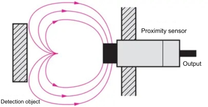
The non-shielded coil magnetic flux surge can increase the detection distance, but because there is no protective enclosure, it is easily affected by surrounding metal.
Special attention is required during installation.
The non-shielded coil magnetic flux surge can increase the detection distance, but because there is no protective enclosure, it is easily affected by surrounding metal.
Special attention is required during installation.
Single shielded type

To prevent signal interference, the distance from the sensor surface to the detected metal material must be ≥ 3Sn (Sn is the sensor detection distance), and the distance between two adjacent proximity sensors must be ≥ D (D is the sensor diameter).

To prevent signal interference, the distance from the sensor surface to the detected metal material must be ≥ 3Sn (Sn is the sensor detection distance), and the distance between two adjacent proximity sensors must be ≥ D (D is the sensor diameter).
Single unshielded type

There is no protection around the induction coil, so the distance Y between the induction surface and the mounting surface must be maintained (M5 to M8, Y = 6 mm; M12, Y = 9 mm).
The distance from the sensor surface to the detected metal material must be ≥ 3Sn, and the distance between two adjacent proximity sensors must be ≥ 2D (D is the sensor diameter).

There is no protection around the induction coil, so the distance Y between the induction surface and the mounting surface must be maintained (M5 to M8, Y = 6 mm; M12, Y = 9 mm).
The distance from the sensor surface to the detected metal material must be ≥ 3Sn, and the distance between two adjacent proximity sensors must be ≥ 2D (D is the sensor diameter).
Opposed mounting method

For sensors installed in opposition, the minimum distance between the two induction surfaces must be ≥ 6Sn

For sensors installed in opposition, the minimum distance between the two induction surfaces must be ≥ 6Sn
Double-distance shielded type

Steel X = 0.2D
Other metals X = 0.1D
*Thickness of detected object: 1 mm

Steel X = 0.2D
Other metals X = 0.1D
*Thickness of detected object: 1 mm
Double-distance non-shielded type


| D dimension | Y (mm) | ||||
| M8 | 12 | ||||
| M12 | 15 |


Precaution
Sensor attenuation coefficient


