Flat Belt Conveyor, Center Drive, External Type, Pulley Dia. 30 mm

Brand :
MISUMI
Caution
Product Description
Dimensional Drawing
E-CVGG/E-CVGH The dimensions shown in the diagram are for belt specification H9 (thickness 0.9 mm); please note that belt thickness varies depending on the belt specification.
Please refer to the flat belt specification list Click here
here
When L ≤ 700, there is no countersunk hole at position F, and 4 nuts are pre-installed on one side in the aluminum profile slot;
When L>700, a countersunk hole for nut insertion is reserved by default at position F, and no additional processing is required.
When selecting a speed control motor, the speed controller is not installed on the main unit and no mounting bracket is provided.
If a bracket for the speed controller is required, please use additional processing (SCB).
*Different power ratings only affect the motor size. For dimension A, please refer to the table below. The external dimensions of other components remain the same.
Nuts are shipped with the conveyor as accessories and are not shown in the CAD model.
Nuts order quantity 1 = 1 pack (50 pcs/pack)
■ Detailed table of A dimensions (variable speed/inverter motor)
■ Detailed table of A dimension (stepper motor)
■ Detailed table of A dimension (servo motor)
■ Detailed Table of Dimension A (Planetary Gearbox)
When selecting a stepper or servo motor with a planetary gearbox, the A dimension shown in the diagram is the sum of the motor A dimension and the planetary gearbox A dimension.
■ Flat belt width - Pulley center distance correspondence table
Motor specifications: 25W*
 Default conveying direction Enlarged view of profile cross-section (symmetrical left and right)
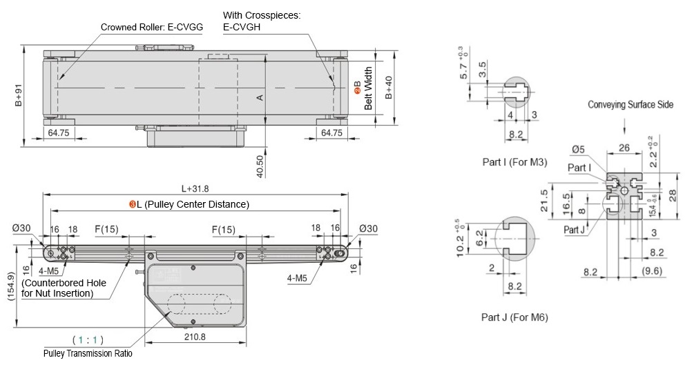
 Default conveying direction Enlarged view of profile cross-section (symmetrical left and right)
 The dimensions shown in the diagram are for belt specification H9 (thickness 0.9 mm); please note that belt thickness varies depending on the belt specification.
Please refer to the flat belt specification list Click
hereWhen L ≤ 700, there is no countersunk hole at position F, and 4 nuts are pre-installed on one side in the aluminum profile slot;When L>700, a countersunk hole for nut insertion is reserved by default at position F, and no additional processing is required.
When selecting a speed control motor, the speed controller is not installed on the main unit and no mounting bracket is provided.If a bracket for the speed controller is required, please use additional processing (SCB).
*Different power ratings only affect the motor size. For dimension A, please refer to the table below. The external dimensions of other components remain the same.
Nut allocation table: L value (center distance unit: mm)
| L355 to 999 | L1000 to 1499 | L1500 or more | Position | Specifications/Model | Configuration Type |
| 8PCS | 12PCS | 16PCS | Section I (left/right) | M3 (hexagonal) / E-HNT-3 (50) | Accessories |
| 8PCS | 12PCS | 16PCS | Section J (left/right) | M6 (square)/E-SNT-6 (50) | Accessories |
Nuts are shipped with the conveyor as accessories and are not shown in the CAD model.Nuts order quantity 1 = 1 pack (50 pcs/pack)■ Detailed table of A dimensions (variable speed/inverter motor)
| Motor power | Motor | Reduction ratio | A | |
| Specifications | Manufacturer | |||
| 6W | Speed control type | Taibang | 3 to 18 | L118 |
| 25 to 180 | L128.5 | |||
| Jingyan | 3 to 18 | L118 | ||
| 25 to 180 | L130 | |||
| 25W | Inverter type | Taibang | 3 to 18 | L118 |
| 25 to 180 | L130 | |||
| Speed control type | 3 to 18 | L129 | ||
| 25 to 180 | L141 | |||
| Inverter type | Jingyan | 3 to 18 | L119 | |
| 25 to 180 | L130 | |||
| Speed control type | 3 to 18 | L129 | ||
| 25 to 180 | L140 | |||
| 40W | Inverter type | Taibang | 3 to 18 | L148 |
| 25 to 180 | L166 | |||
| Speed control type | 3 to 18 | L159 | ||
| 25 to 180 | L177 | |||
| Inverter type | Jingyan | 3 to 18 | L152 | |
| 25 to 180 | L172 | |||
| Speed control type | 3 to 18 | L162 | ||
| 25 to 180 | L182 | |||
■ Detailed table of A dimension (stepper motor)
| Brand | Motor model | A |
| Leadshine stepper motor (open loop) | 57CM23 | L76 |
| 57CM26 | L85 | |
| 57CM31 | L88 | |
| 86CM45 | L80 | |
| 86CM80 | L98 |
■ Detailed table of A dimension (servo motor)
| Servo motor | Brand | A |
| 400W servo motor | Leadshine servo motor | L90.1 |
■ Detailed Table of Dimension A (Planetary Gearbox)
| Gear ratio (x) | Compatible motor specifications | A |
| 3 5 10 | With 400W servo motor | L77 |
| 3 5 10 | With 57 stepper motor | L77 |
| 3 5 10 | With 86 stepper motor | L110 |
When selecting a stepper or servo motor with a planetary gearbox, the A dimension shown in the diagram is the sum of the motor A dimension and the planetary gearbox A dimension.Material Specifications
■ Material Table | Part Name |  Material Material |  Surface Treatment Surface Treatment |
| Profile | Aluminum | Electrophoresis |
| Motor cover | Aluminum | Spray coating and baking |
| Pulley holder | Aluminum | Spray coating and baking |
■ Flat belt width - Pulley center distance correspondence table
| Model | Belt width B | Pulley center distance L | |||||
| L355 to 400 | L405 to 500 | L505 to 600 | L605 to 800 | L805 to 900 | L905 to 2000 | ||
| E-CVGG E-CVGH | 60 to 70 | ● | ● | ● | ● | ● | ● |
| 75 to 110 | ● | ● | ● | ● | ● | ● | |
| 115 to 160 | - | - | ● | ● | ● | ● | |
| 165 to 210 | - | - | - | ● | ● | ● | |
| 215 to 300 | - | - | - | - | - | ● | |
Specification Table
Please follow the selection steps  to
to  , choose the type and parameters, and then place your order.
■ Specifications
■ Speed control/inverter type
When selecting an INV variable frequency motor, the inverter is delivered as an accessory.
■ Stepper type
When using a 57 stepper motor, the driver supports an input voltage of 24 V DC to 48 V DC. (Power supply not included)
When using an 86 stepper motor with a torque of 4.5 N⋅m, the driver supports an input voltage of 48 V DC. (Power supply not included)
When using an 86 stepper motor with a torque of 8.0 N⋅m, the driver supports two types of input voltages: 24 V DC to 70 V DC or 48 V AC to 70 V AC. (Power supply not included)
■ Servo type
When selecting a servo motor, the motor and driver are supplied by default with a single-phase 220 V power supply. In conveyor applications, a motor rated speed of 3000 r/min is used as the standard for calculating linear speed. During use, you can control it as needed through upper-level programming.
The belt thickness is the nominal thickness; the actual thickness is one-tenth of that, in millimeters.
For oil-resistant specifications, only the conveying surface is oil-resistant. If oil gets on the back of the belt, it may not be usable.
When selecting without motor and without gear head, the motor mounting hole spacing will vary depending on the motor output power.
When selecting without motor and without gear head, the main unit will be delivered as parts. Please assemble according to the assembly instructions included in the same package.
For belts other than those above, please refer to the specifications overview by clicking  here.
here.
 to
to  , choose the type and parameters, and then place your order.
 | Type | - |  B Belt width B Belt width | - |  L Pulley center distance L Pulley center distance | - | Motor parameter selection | - |  Belt specification Belt specification | - | Motor brand | ||||
 Output power Output power | - |  Specifications Specifications | - |  Reduction ratio Reduction ratio | |||||||||||
| When there is no belt When there is no motor or gear head | E-CVGG E-CVGG E-CVGG | - - - | 200 200 200 | - - - | 1000 1000 1000 | - - - | 25 25 25 | - - - | SCM INV NM | - - - | 25 25 NH | - - - | H9 J H9 | - - - | G G R |
■ Specifications
| Type | Type | Machine Characteristics |
| E-CVGG | Arc-shaped roller anti-deviation | Good belt flatness and high surface accuracy |
| E-CVGH | Belt with guide strip for anti-deviation | Stable belt anti-deviation, but there is a slight bulge at the bonding area of the center guide strip on the flat belt |
■ Speed control/inverter type
| Type | B Specified unit: 5 mm | L Specified unit: 5 mm | Motor selection | Belt specification (Material is generally PU) | Motor | ||
| Torque (N⋅m)//Power (W) | Specifications | Gear head reduction ratio | |||||
| E-CVGG (Arc-shaped roller type) E-CVGH (Guide strip type) | 60 to 300 | 355 to 2000 | 6 25 40 (Power W) Note: 6 is not suitable for inverter use | SCM (Single-phase 220 V variable speed type) | 5 7.5 10 12.5 15 18 25 30 36 50 60 75 90 100 120 150 180 Note: When the output power is 6, 5–10 are not applicable | H9(General use · Green) W9(General use · White) U5(Sliding use · Green) S5(Sliding use · White) D9(Antistatic use · Black) F12(Food conveying use · White) O9(Oil-resistant type · Green) Q10(Inclined use · Green) Y12(General use · Yellow PVC) V12(General use · Red PVC) J(No belt) | G(Taibang motor) J(Jingyan motor) |
| INV (Three-phase 220 V inverter type) | |||||||
| NM(No motor) | NH(No gear head) | R(No motor · gear head | |||||
When selecting an INV variable frequency motor, the inverter is delivered as an accessory.■ Stepper type
| Type | B Specified unit: 5 mm | L Specified unit: 5 mm | Motor selection | Belt specification (Material is generally PU) | Motor | ||
| Torque (N⋅m)//Power (W) | Specifications | Gear head reduction ratio | |||||
| E-CVGG57 E-CVGG86 (arc roller type) E-CVGH57 E-CVGH86 (with guide bar type) | 60 to 300 | 355 to 2000 | 2.3 2.6 3.1 (57 stepper type / torque N⋅m) | MC(pulse general type) IO(IO control type) EC(EtherCAT bus) RS(RS485) | 3 5 10 NH(no gearhead) Note: 3 to 10 are single-stage | H9(General use · Green) W9(General use · White) U5(Sliding use · Green) S5(Sliding use · White) D9(Antistatic use · Black) F12(Food conveying use · White) O9(Oil-resistant type · Green) Q10(Inclined use · Green) Y12(General use · Yellow PVC) V12(General use · Red PVC) J(No belt) | LS (Leadshine motor) |
| 4.5 8.0 (86 stepper type / torque N⋅m) | |||||||
| NM(no motor or driver) | R(no motor, driver, or gearhead) | ||||||
When using a 57 stepper motor, the driver supports an input voltage of 24 V DC to 48 V DC. (Power supply not included)When using an 86 stepper motor with a torque of 4.5 N⋅m, the driver supports an input voltage of 48 V DC. (Power supply not included)When using an 86 stepper motor with a torque of 8.0 N⋅m, the driver supports two types of input voltages: 24 V DC to 70 V DC or 48 V AC to 70 V AC. (Power supply not included)■ Servo type
| Type | B Specified unit: 5 mm | L Specified unit: 5 mm | Motor selection | Belt specification (Material is generally PU) | Motor | ||
| Torque (N⋅m)//Power (W) | Specifications | Gear head reduction ratio | |||||
| E-CVGG4 (arc roller type) E-CVGH4 (With guide bar type) | 60 to 300 | 355 to 2000 | 400 (Servo type, power W) | MC(Pulse universal type) EC(Bus EtherCAT) | 3 5 10 NH(no gearhead) Note: 3 to 10 are single-stage | H9(General use · Green) W9(General use · White) U5(Sliding use · Green) S5(Sliding use · White) D9(Antistatic use · Black) F12(Food conveying use · White) O9(Oil-resistant type · Green) Q10(Inclined use · Green) Y12(General use · Yellow PVC) V12(General use · Red PVC) J(No belt) | LS (Leadshine motor) |
| NM(no motor or driver) | R(no motor, driver, or gearhead) | ||||||
When selecting a servo motor, the motor and driver are supplied by default with a single-phase 220 V power supply. In conveyor applications, a motor rated speed of 3000 r/min is used as the standard for calculating linear speed. During use, you can control it as needed through upper-level programming.The belt thickness is the nominal thickness; the actual thickness is one-tenth of that, in millimeters.For oil-resistant specifications, only the conveying surface is oil-resistant. If oil gets on the back of the belt, it may not be usable.When selecting without motor and without gear head, the motor mounting hole spacing will vary depending on the motor output power.When selecting without motor and without gear head, the main unit will be delivered as parts. Please assemble according to the assembly instructions included in the same package.For belts other than those above, please refer to the specifications overview by clicking  here.
here.Table 1: Gearhead reduction ratio & conveying capacity (variable speed/inverter motor)
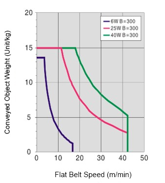
Test motor: Jingyan (J) synchronous pulley transmission ratio 1:1
Belt width: B = 300 mm, thickness 0.9 mm Roller center distance: L = 2000 mm
 Test motor: Jingyan (J) synchronous pulley transmission ratio 1:1
Belt width: B = 300 mm, thickness 0.9 mm Roller center distance: L = 2000 mm
■ Gearhead reduction ratio
INV inverter type: When motor speed is 1300 rpm (50 Hz)
Reference values for flat belt speed.
May decrease depending on load conditions
INV inverter type: When motor speed is 1300 rpm (50 Hz)Reference values for flat belt speed.
| Gearhead Reduction ratio | Flat belt speed (m/min) | |
| SCM variable speed type | INV inverter type | |
| 5 | 26.4 to 42.4 | 24.5 to 40.8 |
| 7.5 | 17.6 to 29.3 | 16.3 to 27.2 |
| 10 | 13.2 to 22.0 | 12.2 to 20.4 |
| 12.5 | 10.6 to 17.6 | 9.8 to 16.3 |
| 15 | 8.8 to 14.7 | 8.2 to 13.6 |
| 18 | 7.3 to 12.2 | 6.8 to 11.3 |
| 25 | 5.3 to 8.8 | 4.9 to 8.2 |
| 30 | 4.4 to 7.3 | 4.1 to 6.8 |
| 36 | 3.7 to 6.1 | 3.4 to 5.7 |
| 50 | 2.6 to 4.4 | 2.4 to 4.1 |
| 60 | 2.2 to 3.7 | 2.0 to 3.4 |
| 75 | 1.8 to 2.9 | 1.6 to 2.7 |
| 90 | 1.5 to 2.4 | 1.4 to 2.3 |
| 100 | 1.3 to 2.2 | 1.2 to 2.0 |
| 120 | 1.1 to 1.8 | 1.0 to 1.7 |
| 150 | 0.9 to 1.5 | 0.8 to 1.4 |
| 180 | 0.7 to 1.2 | 0.7 to 1.1 |
May decrease depending on load conditionsTable 2: Load and linear speed correspondence table (stepper motor)
Leadshine (LS) synchronous pulley transmission ratio 1:1
Belt width: B = 200 mm, thickness 0.9 mm Roller center distance: L = 1000 mm
Table 3: Correspondence Table of Load and Linear Speed (Servo Motor)
Leadshine (LS) synchronous pulley transmission ratio 1:1
Belt width: B = 200 mm, thickness 0.9 mm Roller center distance: L = 1000 mm
*Reference value
| Speed (rpm) | Gearhead Reduction ratio | Recommended maximum line speed (m/min) | Voltage 24 V DC (current 5 A) | Voltage 48 V DC (current 6 A) | |||
| 57CM23 | 57CM26 | 57CM31 | 86CM45 | 86CM80 | |||
| Load (kg) | |||||||
| 100 | NH | 15.7 | 0.5 | 1 | 2 | 4.5 | 8.5 |
| 200 | 31.4 | 0.5 | 0.5 | 1.5 | 3 | 6.5 | |
| 200 | 3 | 10.5 | 5.5 | 6 | 10 | 15 | 15 |
| 5 | 6.3 | 15 | 15 | 15 | 15 | 15 | |
| 10 | 3.1 | 15 | 15 | 15 | 15 | 15 | |
Leadshine (LS) synchronous pulley transmission ratio 1:1Belt width: B = 200 mm, thickness 0.9 mm Roller center distance: L = 1000 mm
Table 3: Correspondence Table of Load and Linear Speed (Servo Motor)
*Reference value
| Speed (rpm) | Gear head reduction ratio | Recommended maximum linear speed (m/min) | Voltage 220 V AC |
| 400W | |||
| Load (kg) | |||
| 3000 | NH | 100 | 1 |
| 3 | 100 | 15 | |
| 5 | 94.2 | 15 | |
| 10 | 47.1 | 15 |
Leadshine (LS) synchronous pulley transmission ratio 1:1Belt width: B = 200 mm, thickness 0.9 mm Roller center distance: L = 1000 mm
Alterations
 | Type | - | B Belt width | - | L Pulley center distance | - | Motor parameter selection | - | Belt specification | - | Motor brand | - | Alteration | ||||
| Output power | - | Specifications | - | Reduction ratio | |||||||||||||
| E-CVGG | - | 200 | - | 1000 | - | 25 | - | SCM | - | 25 | - | H9 | - | G | - | MP200 | |
| Alterations | Code | Spec | ||||||
Drive unit position specification | MP | The drive unit installation position can be changed. Ordering Code MP 155 ≤ MP ≤ L-335 *Minimum value of L is 490 Only the center drive type can be specified. | ||||||
Mounting bracket for speed controller | SCB | Comes with a mounting bracket for the speed controller. Ordering Code SCB | ||||||
Reverse conveyor operation Not suitable for reverse operation when B value < 100 and L value > 1500 Not suitable for reverse operation when B value < 100 and L value > 1500 | FX | Reverse operation. Ordering Code FX | ||||||
Increase the number of nuts  Select only when the standard quantity is insufficient (see dimensional drawing for standard quantity and specifications) Select only when the standard quantity is insufficient (see dimensional drawing for standard quantity and specifications) | ANQ | Increase the number of nuts. Ordering Code ANQ5
|
Product Features
Feature 1: Uses an external drive design for easy installation and maintenance, suitable for multi-line connection scenarios.
Feature 2: Lightweight model supports customizable length specification.
Feature 3: Flexible structure allows for quick adaptation to different production line connection requirements.
Feature 2: Lightweight model supports customizable length specification.
Feature 3: Flexible structure allows for quick adaptation to different production line connection requirements.
Precautions
(1) Do not disassemble or modify the conveyor by yourself to avoid performance issues.
(2) Due to differences in the operating environment, MISUMI conveyors do not come with a power supply, cables, or switches.
(3) Due to issues with the structural strength and deformation of the conveyor body, please do not exceed the allowable load or length and width when selecting a model.
(4) The motor is available in two voltage specifications: single-phase 220 V and three-phase 220 V. Please select the voltage according to your requirements.
(5) Belt misalignment is a normal occurrence and is not considered a quality issue. Adjusting for misalignment is a part of routine maintenance.
(6) Misalignment tolerance: The distance between the belt and both sides of the roller should be 5+/-3mm. During operation, it is not possible to ensure that the belt always stays exactly in the center of the aluminum frame. For the belt misalignment adjustment method, clickhere.
(7) If the direction of operation is opposite to the standard direction, abnormal conditions such as belt misalignment, belt damage, noise, or jamming may occur. Please avoid using it in this way. (The standard transport direction is shown below)

(2) Due to differences in the operating environment, MISUMI conveyors do not come with a power supply, cables, or switches.
(3) Due to issues with the structural strength and deformation of the conveyor body, please do not exceed the allowable load or length and width when selecting a model.
(4) The motor is available in two voltage specifications: single-phase 220 V and three-phase 220 V. Please select the voltage according to your requirements.
(5) Belt misalignment is a normal occurrence and is not considered a quality issue. Adjusting for misalignment is a part of routine maintenance.
(6) Misalignment tolerance: The distance between the belt and both sides of the roller should be 5+/-3mm. During operation, it is not possible to ensure that the belt always stays exactly in the center of the aluminum frame. For the belt misalignment adjustment method, click
here.(7) If the direction of operation is opposite to the standard direction, abnormal conditions such as belt misalignment, belt damage, noise, or jamming may occur. Please avoid using it in this way. (The standard transport direction is shown below)

Application Example
| Equipment Manufacturing | Semiconductors | Lithium batteries | ||
 |  |  | ||
| Food | Electronics and Electrical Appliances | Robotics | ||
 |  |  |
Related Documents Click here
here