M3.5 Screw Lock
Caution
Product Description
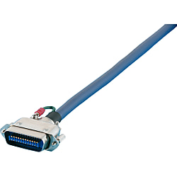
A series that uses Centronics connectors (solder type) manufactured by Daiichi Denshi Kogyo (DDK) and cables manufactured by Misumi. Connection is M3.5 screw lock. Lineup of 24, 36 and 50 cores. Can be used to connect various control devices, printers, etc.
[Features]
·Connector hood: Daiichi Denshi Kogyo (DDK) centronics connector solder type
·Cable: Double-shielded, thin flexible, oil-resistant, and a wide variety of cable types (6 types) to choose from. The cable is twisted pair.
·mating: M3.5 screw lock type
·Overall Length: The length can be specified in 0.1 m increments from a minimum of 0.2 m to a maximum of 50 m.
·Free combination with male connectors on both ends, Y terminal on one side, etc.

● Cables that feature the Centronics connector that can be used for the connection of various control devices. EMI-countermeasure model cables that feature the shielded twisted pair cable for the cable, and the M3.5 screw lock model hood for the connector.

· Small diameter cables support 30V.
· It cannot be connected with the spring lock model.
· When the mark tube has no printed custom number specified, the connector pin arrangement number is printed.
· Sheath peeling length can be designated as alteration service only for those with terminals or mark tubes.
· Specifying the length of the connector side ground cable is not supported.
· The shield is connected to the hood.
· The combination of the Centronics connector and other connectors' combination cables can be handled with the "Web Design Harness Plus."
Wiring and Wire Color Page
>>Click here
Component Page
>>Click here
Specifications

| L (m) | ~ 0.9 | 1 ~ 4 | 4.1 ~ 50 |
| Tolerance | +20mm | +50mm | + 3% of Total Length |
| Connector Type | Shape Specification Type | Outline Image Drawing (Unit: mm) | Cable Type | Number of Cores | Specified Length (m) |
| ND76 EMI Countermeasure Type Solder Type Connector M3.5 Screw Lock Type DDK | P (Male) |  |      | 24 | 0.2 ~ 50 Can be specified by 0.1m increments |
| 36 | |||||
| 50 | |||||
| PP (Male / Male) |  | 24 | |||
| 36 | |||||
| 50 | |||||
| PY (Male / Y Terminal F0.3-3 equivalent product) With Pin No. Insertion Mark Tube |  | 24 | |||
| 36 | |||||
| 50 | |||||
| PT (Male / Loose Wires) With Pin No. Insertion Mark Tube |  | 24 | |||
| 36 | |||||
| 50 |
* - is not available.
Material / Finish
| Item | Materials | Finish |
|---|---|---|
| Insulator (RC Type) | Glass-Filled Polybutylene Terephthalate | UL94V-0, Blue |
| Insulator (Type 57, Angle Type) | DAP Resin | UL94V-0, Blue |
| Contact | Copper Alloy | Nickel Base Gold Plating |
| Shell | Steel | Nickel-plated |
| Hood (Angle Type Only) | Aluminum Alloy | Rustproofing Treatment |
| Spring Latch | Stainless Steel | - |

| Item | Materials | Finish |
|---|---|---|
| Insulator | PC Resin | UL94V-0, Blue |
| Contact | Copper Alloy | Nickel Base Gold Plating |
| Shell (57FE-40 only) | Brass | Nickel-plated |
| Strain Relief | PC Resin | UL94V-0, Blue |
| Earth Plate (57FE-30 only) | Brass | Nickel-plated |
| Spring Latch (57FE-40 only) | Stainless Steel | - |
| Metal Hood (57FE-30 only) | Aluminum Alloy | Rustproofing Treatment |

* 57F series is made up of 4 components: insulator, contact, strain relief, and pressure welding cover.
Compatible Wire
| Connector Type | Single Wire Conductor Diameter | Stranded Wire Conductor Cross-sectional Area | AWG Size |
|---|---|---|---|
| Soldering Type | 0.65 mm or less | 0.2 mm2 or less | Stranded Wire AWG24 or less Single Wire AWG22 or less |
| Pressure Welding Type | - | - | AWG26 (Single Wire), AWG28 (Stranded Wire, Single Wire) or AWG30 (Single Wire) 1.27 mm Pitch Flat Cable |
Electrical Properties
| Item | Soldering Type | Pressure Welding Type |
|---|---|---|
| Rated Current | 5 A or lower | 1 A or lower |
| Rated Voltage | 500 VAC or less | 250 VAC or less |
| Contact Resistance | 35 mΩ or less / 1 ADC | 35 mΩ or less / 1 ADC |
| Insulation Resistance | 1,000 MΩ or more / 500 VDC | 1,000 MΩ or more / 500 VDC |
| Withstand Voltage | 1,000 VAC / minute | 500 VAC / minute |
| Operating Temperature Range | -55°C ~ +105°C | -55°C ~ +105°C |
Mechanical Properties
| Item | Characteristics | Conditions |
|---|---|---|
| Insertion and Extraction Force Per Single Pole | Insertion Force: 112 g or less, Extraction Force: 86 g or less | When the plug and socket are inserted and extracted, the total extraction force is divided by each core number to convert into force per single pole |
| Vibration Resistance | · No interruption to power supplies of 1 μs or more · No abnormalities such as damage etc. on the connector | In compliance with MIL-STD-202 test method condition 204 A, simple vibration with smaller amplitude, either the total amplitude of 1.52 mm from 10 Hz to 500 Hz or 10 G (gravity units) is applied to each for 3 hours in mutually perpendicular 3-axis direction. |
| Impact Resistance | No cracks in the connector or abnormalities such as loosening in breakable parts | Impact of 50 G with duration 11 msec is applied to the coupled connector in mutually perpendicular axis direction. |
| Insertion and Removal Durability | No mechanical damage | Perform insertion and removal 500 times at speeds not exceeding 500 times per 1 hour. |
Environmental Properties
| Item | Characteristics | Conditions |
|---|---|---|
| Temperature Resistance | There should be no physical damage or obstacle when inserting or removing the connector | Repeatedly expose to temperatures +85°C and -55°C for 30 minutes 5 times each. However, do not expose to room temperature for 5 minutes or more when moving from low temperature to high and from high temperature to low. |
| Humidity Resistance | · There should be no mechanical damages · Voltage Resistance 300 VAC 1 minute | Perform 96-hour humidity test with the connector detached in compliance with MIL-STD-202 test method 103 B. |
| Corrosion Resistance | There should be no significant corrosion or obstacle when inserting or removing the connector | After performing a 48-hour salt spray test with the connector attached in compliance with MIL-STD-202 test method condition 101 B, the connector is uncoupled, washed, and dried for 12 hours in a drying oven at 38°C. |
Contact Arrangement Diagram

This diagram is a view of the socket (female) connector from the coupling.
The plug (male) will be reversed on the left and right.