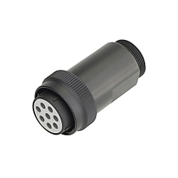
NB01/CE01 Waterproof Straight Plug (Bayonet Lock)
Caution
Product Description
[Features]This is a waterproof type straight plug. You can choose from 2 types: the soldering type, which requires no tools, and the crimping type, which has good work efficiency. It locks into place with a half twist. IP67 compliant waterproofness and dust-proofness. A straight plug that can be connected to a panel-mount receptacle and an inline adapter. A semi-twisted bayonet lock with a special spring structure makes it easy to confirm secure mating. [Applications]Since it has an IP67 class waterproof structure when mated, it is suitable for use in locations exposed to water or oil.

● Straight plugs capable of connecting with panel mount receptacles and relay adapters.
● The special spring structure allows the secure fitting to be easily confirmed by a half twist of the bayonet lock.
● It has a waterproof fitting structure class IP67, which makes it suitable for use in places exposed to water or oil.

· The crimp model (CE0106A) contact is sold separately.
· The cable outlet is not designed to hold the cable.
· Use in combination with a waterproof cable clamp.
· Straight plugs cannot be fitted with one another.
· CE01 series are DDK products sold with Misumi model numbers.
Specifications

| Wire Connection Type | Arrangement No. | Contact Shape | Cable Drawing Out Direction | Number of Cores | Shell Size | Contact Size |
| NB0106A Solder Connection CE0106A Crimp Connection | 18-1 | P Male (Pin) S Female (Socket) | DBSS (Straight) | 10 | 18 | #16 |
| 18-11 | 5 | 18 | #12 | |||
| 20-15 | 7 | 20 | #12 | |||
| 20-29 | 17 | 20 | #16 | |||
| 22-14 | 19 | 22 | #16 | |||
| 22-22 | 4 | 22 | #8 | |||
| 22-23 | 8 | 22 | #12 | |||
| 24-10 | 7 | 24 | #8 | |||
| 24-28 | 24 | 24 | #16 | |||
| 28-21 | 37 | 28 | #16 | |||
| CE0106A Crimp Connection | 18-19A | 19 | 18 | #20 | ||
| 20-30A | 30 | 20 | #20 | |||
| 24-52A | 52 | 24 | #20 | |||
| 28-73A | 73 | 28 | #20 |
Protection Circuit Connection Structural Diagram

About Compatible Products
NB01 connectors, CE01 connectors, and JL05 connectors are compatible with each other.Combination Method


Material / Finish
| Item | Materials | Finish |
|---|---|---|
| Shell (Body) | Aluminum Alloy | Black Chromate Treatment |
| Insulator | Polyester Resin | UL94V-0, Gray |
| Contact | Copper Alloy | Silver Plating |
| O-ring | Nitrile Rubber | Black |
| Coupling Nut | Aluminum Alloy | Black Chromate Treatment |
| Earth Lug | Steel Alloy | Silver Plating |
| Rear Gasket for Flange | Chloroprene Rubber | Black |
Electrical and Mechanical Properties, Compatible Wires
| Item | Characteristics | |||||||
|---|---|---|---|---|---|---|---|---|
| Rated Current | Contact Size | #20 | #16 | #12 | #8 | |||
| Maximum Value per 1 Piece | 5 A | 13 A | 23 A | 46 A | ||||
| Rated Voltage | Rating Classification | AC (r.m.s) | DC | |||||
| INST | 200 | 250 | ||||||
| A | 500 | 700 | ||||||
| D | 900 | 1,250 | ||||||
| Withstand Voltage | INST | 1,000 VAC (r.m.s) 1 minute | ||||||
| A | 2,000 VAC (r.m.s) 1 minute | |||||||
| D | 2,800 VAC (r.m.s) 1 minute | |||||||
| Insulation Resistance | 5,000 MΩ or more at 500 VDC | |||||||
| Contact Resistance | Contact Size | #20 | #16 | #12 | #8 | |||
| mΩ or less | 8 | 4 | 2 | 0.6 | ||||
| Operating Temperature Range | -55°C ~ +125°C | |||||||
| Waterproofing | IP67 Equivalent | |||||||
| Humidity | Relative Humidity 95% or less | |||||||
| Service Life | 500 Insertions and Removals | |||||||
| NB01 (Solder Type) Compatible Wires (Note 2) | Contact Size | #16 | #12 | #8 | ||||
| Conductor Cross-sectional Area | 0.75 mm2 or less | 3.5 mm2 or less | 8 mm2 or less | |||||
| AWG Size | 18 or less | 12 or less | 8 or less | |||||
(Note 1) Rated voltage and voltage resistance are shown with rating classification symbols (INST, A; D). Refer as well to the table below.
Contact Arrangement Diagram
| Number of Contacts | 4 | 5 | 7 | 7 | 8 |
|---|---|---|---|---|---|
| Arrangement No. | 22-22 | 18-11 | 20-15 | 24-10 | 22-23 |
| Contact Size | #8 | #12 | #12 | #8 | #12 |
| Contact Arrangement (Note 1) (Note 2) |
 |
 |
 |
 |
 |
| Rating Classification | A | A | A | A | D (4), A (Others) |
| Number of Contacts | 10 | 17 | 19 | 19 | 24 |
|---|---|---|---|---|---|
| Arrangement No. | 18-1 | 20-29 | 18-19A | 22-14 | 24-28 |
| Contact Size | #16 | #16 | #20 | #16 | #16 |
| Contact Arrangement (Note 1) (Note 2) |
 |
 |
 |
 |
 |
| Rating Classification | A (3, 5, 6, 8), INST (Others) | A | INST | A | INST |
| Number of Contacts | 30 | 37 | 52 | 73 |
| Arrangement No. | 20-30A | 28-21 | 24-52A | 28-73A |
| Contact Size | #20 | #16 | #20 | #20 |
| Contact Arrangement (Note 1) (Note 2) |
 |
 |
 |
 |
| Rating Classification | INST | A | INST | INST |
|---|
(Note 1) View from the male (pin) connector coupling surface.
(Note 2) The ○ in the arrangement table shows the earth terminals (for protection of terminal connections).
Panel Cut Size Drawing

| Compatible Shell Size | φA ±0.5 | φB +0.2 -0 | C ±0.13 | Mounting Screws (Reference) | Rear Mounting Panel Thickness Limit | |
|---|---|---|---|---|---|---|
| Inch Screws | Metric Screws | |||||
| 18 | 30.2 | 3.3 | 26.97 | #4-40 | M3 | 3.0 or less |
| 20 | 34.9 | 3.3 | 29.36 | #4-40 | M3 | |
| 22 | 36.6 | 3.3 | 31.75 | #4-40 | M3 | |
| 24 | 39.7 | 4.3 | 34.92 | #6-32 | M4 | |
| 28 | 46.1 | 4.3 | 39.67 | #6-32 | M4 | |