NRW Waterproof Cap
Brand :
MISUMI
Caution
Product Description
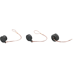
There are 3 types, one for straight plugs, one for panel-mount receptacles, and one for inline adapters, to prevent dust and contaminant from entering the mating part when the connector is not connected.

● Prevents intrusion of dust and foreign matter when not connected.
● Three models: for straight, for relay, and for panel mounting.
Specifications

| Model | Shell Size | Shape Symbol | Weight (g) |
| NRW | 20 | PCA-1 For Straight | 5 |
| 24 | 6 | ||
| 28 | 10 | ||
| 20 | RCA-1 For Panel Mounting | 10 | |
| 24 | 14 | ||
| 28 | 21 | ||
| 20 | ADCA-1 For Relay | 12 | |
| 24 | 14 | ||
| 28 | 21 |
Features
● NRW series connectors are round connectors, designed to enhance water-proofing functionality when connected. (IP67 equivalent)● Superior weather and impact resistance due to the high-strength plastic material used.
● NRW series products are suitable for power supplies.
● There are 3 types of connectors: Straight, relay, and panel mount connectors.
● Because these connectors are connected by soldering, no dedicated tool is required for wiring.

Materials / Finish
| Item | Materials | Finish |
|---|---|---|
| Shell | Synthetic Resin | - |
| Insulator | Synthetic Resin | - |
| Contact | Copper Alloy | Silver Plated |
| Packing | Synthetic Rubber | - |

Characteristics
| Item | Contents |
|---|---|
| Rated Current | Check with the table below. |
| Rated Voltage | Check with the table below. |
| Withstand Voltage | No abnormality such as short circuiting occurs when regulated voltage is applied for 1 minute between immediately adjacent conductors. |
| Insulation Resistance | 1,000 MΩ or higher when measured between immediately adjacent conductors with regulated voltage. |
| Contact Resistance | Conductor resistance is 5 mΩ or less when a pair of contacts are connected at up to the regulation length. |
| Vibration Resistance | No functional defect was found during the JIS C 5025 vibration test. Contact resistance is 5 mΩ or less. |
| Impact Resistance | No functional defect was found during the JIS C 5026 shock test. Contact resistance is 5 mΩ or less. |
| Repeated Operation | No functional defect was found when a removal and insertion sequence was tested 500 times. Contact resistance is 5 mΩ or less. |
| Humidity Resistance | No functional defect was found during the JIS C 5023 humidity test. Insulation resistance is 100 MΩ. |
| Temperature Cycle | No functional defect was found during the JIS C 5030 temperature cycle test. |
| Corrosion Resistance | No functional defect was found during the JIS C 5028 salt water spray test. Contact resistance is 5 mΩ or less. |
| Waterproofing | No abnormality such as flooding was found when left under water pressure of 0.4 kgf/cm2 at regular working conditions for 24 hours or more. |
| Operating Temperature Range | -25°C ~ +85°C |
Table of Basic Specifications
| Product No. | Shell Size | Number of Cores | Shape Symbol | Rated Current (A or less) | Rated Voltage (V or less) | Withstand Voltage AC (V) | Insulation Resistance (MΩ or higher) | Contact Resistance (mΩ or less) | Compatible Wire Size | Applicable Electric Wire Finished Outer Diameter (mm) Note 1 | |
|---|---|---|---|---|---|---|---|---|---|---|---|
| AWG | Conductor Section Area mm2 | ||||||||||
| NRW | 20 | 2, 3 | PF, RM, ADM | 15 | 250 | 1,500 | 2,000 | 3 | 14 | 2 | 7.0 ~ 12.5 |
| 4, 5 | 10 | 16 | 1.25 | ||||||||
| 7 | 1,000 | ||||||||||
| 12 | 5 | 1,000 | 5 | 20 | 0.5 | ||||||
| 20 | 2, 3 | PM, RF, ADF | 15 | 250 | 1,500 | 2,000 | 3 | 14 | 2 | 7.0 ~ 12.5 | |
| 4, 5 | 10 | 16 | 1.25 | ||||||||
| 7 | 1,000 | ||||||||||
| 12 | 5 | 1,000 | 5 | 20 | 0.5 | ||||||
| 24 | 2, 3 | PF, RM, ADM | 20 | 250 | 1,500 | 5,000 | 3 | 12 | 3.5 | 9.5 ~ 15.0 | |
| 4, 5 | 15 | 14 | 2 | ||||||||
| 10 | 10 | 1,000 | 2,000 | 16 | 1.25 | ||||||
| 14, 16 | 5 | 1,000 | 5 | 20 | 0.5 | ||||||
| 24 | 2, 3 | PM, RF, ADF | 20 | 250 | 1,500 | 5,000 | 3 | 12 | 3.5 | 9.5 ~ 15.0 | |
| 4, 5 | 15 | 14 | 2 | ||||||||
| 10 | 10 | 1,000 | 2,000 | 16 | 1.25 | ||||||
| 14, 16 | 5 | 1,000 | 5 | 20 | 0.5 | ||||||
| 28 | 16 | PF, RM, ADM | 10 | 250 | 1,000 | 2,000 | 3 | 16 | 1.25 | 12.5 ~ 18.0 | |
| 24 | 5 | 1,000 | 5 | 20 | 0.5 | ||||||
| 28 | 16 | PM, RF, ADF | 10 | 250 | 1,000 | 2,000 | 3 | 16 | 1.25 | 12.5 ~ 18.0 | |
| 24 | 5 | 1,000 | 5 | 20 | 0.5 | ||||||
Note 1: Even connectors with the same shell sizes may be divided into 2 or 3 types depending on the thickness of the cable used. Take care at selection. Refer to each product page for further details.
Contact Arrangement Diagram

Connection Work Method

