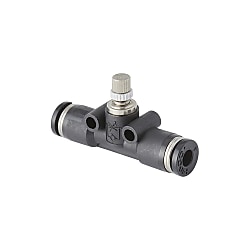
Speed controller, compact union straight
Caution
- The product images are representative only. Specifications may vary by part number, including shape and color.
Product Description
Standard speed control valve for drive equipment.
[Features]
· It is suitable for space saving piping.
· The compact union type has been renewed.
· Clear zero point at fully closed setting and improved operability in the low flow rate range.
[Applications]
· Assembly equipment, filling machines, automatic packaging machines, molded product ejection
Drawing

Product Specification
Product Specification
Fluid: Air
Operating pressure range: 0.1 to 0.9 MPa (spring return specification: 0.05 to 0.5 MPa), 0.05 to 1.0 MPa (JSMU type)
Check valve operating pressure: 0.05 MPa (spring return specification: 0.02 MPa), 0.005 MPa (JSMU type)
Operating temperature range: 0 to +60°C (no freezing)
Compatible Size
Tube size| Metric size (mm) | ⌀3, ⌀4, ⌀6, ⌀8, ⌀10, ⌀12 |
|---|---|
| Inch size | ⌀1/8, ⌀5/32, ⌀3/16, ⌀1/4, ⌀5/16, ⌀3/8, ⌀1/2 |
| metric thread | M3 x 0.5, M5 x 0.8 |
|---|---|
| Tapered pipe thread | R1/8, R1/4, R3/8, R1/2 |
Specifications Table
| Type | Tube outer diameter ⌀D | B1 | B2 | ⌀p | T | C | ⌀d | F1 | F2 | Weight (g) | |
|---|---|---|---|---|---|---|---|---|---|---|---|
| MAX | MIN | ||||||||||
| JSMU4 | 4 | 21 | 18.6 | 21 | 10 | 10.5 | 14.9 | 3.2 | 12.7 | 4.8 | 9 |
| JSMU6 | 6 | 25.8 | 21.6 | 24.4 | 12.5 | 13.1 | 17 | 3.2 | 14.8 | 6.2 | 14 |
| JSMU8 | 8 | 30.6 | 25.1 | 28 | 14.8 | 15.4 | 18.1 | 3.2 | 18.2 | 7.2 | 27 |
| JSMU10 | 10 | 35.4 | 28.9 | 31.8 | 18.2 | 19.7 | 20.2 | 4.2 | 22.2 | 8.7 | 48 |
| JSMU12 | 12 | 38 | 31.5 | 36.9 | 21.2 | 22.7 | 23.4 | 4.2 | 25.7 | 10.2 | 68 |
| JSMU5/32 | 5/32 | 21 | 18.6 | 21 | 10 | 10.5 | 14.9 | 3.2 | 12.7 | 4.8 | 9 |
| JSMU1/4 | 1/4 | 25.8 | 21.6 | 24.4 | 12.5 | 13.1 | 17 | 3.2 | 14.8 | 6.2 | 14 |
| JSMU5/16 | 5/16 | 30.6 | 25.1 | 28 | 14.8 | 15.4 | 18.1 | 3.2 | 18.2 | 7.2 | 27 |
| JSMU3/8 | 3/8 | 35.4 | 28.9 | 31.8 | 18.2 | 19.7 | 20.2 | 4.2 | 22.2 | 8.7 | 48 |
| JSMU1/2 | 1/2 | 38 | 31.5 | 37.2 | 21.2 | 22.7 | 23.7 | 4.2 | 25.7 | 10.2 | 67 |
- *External appearance color: other than black and regular packaging, select and enter the symbol from the following.
For external appearance color: light gray, symbol: W, and for packaging specification: clean room packaging, symbol: -C,
For external appearance color: light gray and packaging specification: cleanroom packaging, Symbol: W-C
Usage Example
Speed adjustment methods
1. Speed Adjustment of Drive Equipment

(1). When increasing the speed
Turning the needle of the speed controller counterclockwise from the fully closed position will increase the speed of the drive equipment. Once the desired speed is reached, be sure to tighten the lock nut to prevent the speed setting from going out of alignment.
(2) Slowing down the speed
If you turn the speed controller needle too much (if the speed becomes too fast), turn it clockwise to slow it down. Once the desired speed is reached, be sure to tighten the lock nut to prevent the speed setting from going out of alignment.How To Attach And Detach The Connecting Part
1. How to attach/detach the tube

(1) Tube attachment
In the speed controller (speed control valve with quick connect fitting), simply insert the tube into the tube stop, the lock claws secure the tube, and the elastic sleeve seals the outer circumference of the tube.
(2) Tube removal
To remove the tube, push the release ring to open the lock claws and remove the tube. Be sure to stop the air before removing the tube.2. Screw Tightening Method

(1) Tightening the screws
To tighten the thread, tighten the hexagonal outer diameter with a wrench.
(1) Tightening the screws
There are two types of thread-tightening methods: one is to tighten the hexagonal outer diameter with a wrench, and the other is to tighten the upper slot with a straight-slot screwdriver.Product Feature Details

Rotating of resin main body, rotating of fitting

Rotating of Resin main body A

Rotating of fitting body

Rotating of Resin main body B

Controlling Direction Indication of Resin Body
Cautions and Prohibitions
Cautions and Prohibitions
1. Selection of pneumatic equipment
(1) The selection of pneumatic equipment should be decided by a person who has sufficient knowledge and experience, such as a pneumatic system designer or a person who decides specifications.
(2) Since there are various usage conditions, the suitability for the system should be determined by a person with sufficient knowledge and experience, such as a pneumatic system designer or a person who decides specifications, after conducting analysis or testing as necessary. In addition, responsibility for ensuring the intended performance and safety of this system lies with the person who determined the system's suitability. When configuring your system, please review all specifications using the latest documentation, and consider possible equipment failures.
2. A person with sufficient knowledge and experience should handle the pneumatic equipment.
(1) Compressed air can be dangerous if handled improperly. Assembly, operation, maintenance, etc., of machines and devices using pneumatic equipment should be performed by persons with sufficient knowledge and experience.
3. Please do not handle machines/devices or remove equipment until safety is confirmed.
(1) Before inspecting or servicing machines/devices, make sure that workpiece fall prevention measures are taken and runaway prevention devices, etc. are installed.
(2) Before removing the equipment, make sure that the above safety measures are taken, shut off the supply of compressed air and the power supply of the corresponding equipment, and exhaust the compressed air in the system.
(3) When restarting the machine/device, be careful and make sure that measures are taken to prevent popping out.
- *Please note that cautions and prohibited items are subject to change without notice.