Standard Type, Throttle Valve, Elbow
Caution
Product Description
Controls pneumatic equipment speed and air pressure signals.
Specifications Of Standard Type Throttle Valve - Elbow

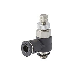
Appearance of Standard Type Throttle Valve - Elbow

Dimensional drawing of Standard Type Throttle Valve - Elbow

Release Ring Mini Type

Release Ring Mini Type
| Format | Tube Outer Diameter øD | R | A | B | L1 | L2 | øp1 | øP2 | Tube End C | E | Hex H | X (øX) | Y | Mass (g) | ||
|---|---|---|---|---|---|---|---|---|---|---|---|---|---|---|---|---|
| Max. | Min. | Max. | Min. | |||||||||||||
| JNC4-M5□ | 4 | M5 × 0.8 | 2.9 [3.2] | 29.7 | 27 | 26.8 [26.5] | 24.1 [23.8] | 6.7 [6.4] | 8 | 9.8 | 11 | 15.4 | 8 | 9.8 | 7.8 | 7.9 |
| JNC4-01□ | R1/8 | 8 | 41.5 | 35.1 | 37.5 | 31 | 10.7 | 14.4 | 17.7 | 10 | 18 | |||||
| JNC6-M5□ | 6 | M5 × 0.8 | 2.9 [3.2] | 29.7 | 27 | 26.8 [26.5] | 24.1 [23.8] | 7.5 [7.2] | 10.5 | 9.8 | 11.6 | 17.5 | 8 | 11.8 | 9.8 | 8.6 |
| JNC6-01□ | R1/8 | 8 | 41.5 | 35.1 | 37.5 | 31.1 | 10.7 | 14.4 | 18.3 | 10 | 19 | |||||
| JNC6-02□ | R1/4 | 11.1 | 49.2 | 42.1 | 43.1 | 36 | 11.9 | 18.4 | 20.2 | 14 | 37 | |||||
| JNC8-01□ | 8 | R1/8 | 8 | 41.5 | 35.1 | 37.5 | 31.1 | 11.9 | 14.4 | 14.4 | 18.1 | 26.9 | 10 | 13.8 | - | 22 |
| JNC8-02□ | R1/4 | 11.1 | 49.2 | 42.1 | 43.1 | 36 | 13.2 | 18.4 | 28.4 | 14 | 40 | |||||
| JNC8-03□ | R3/8 | 13.2 | 55.5 | 47.3 | 49.1 | 40.9 | 15.4 | 22 | 28.9 | 19 | 71 | |||||
| JNC10-02□ | 10 | R1/4 | 11.1 | 49.2 | 42.1 | 43.1 | 36 | 14.8 | 17.6 | 18.4 | 20.2 | 30.9 | 14 | 16.8 | - | 44 |
| JNC10-03□ | R3/8 | 13.2 | 55.5 | 47.3 | 49.1 | 40.9 | 16.7 | 22 | 31.2 | 19 | 74 | |||||
| JNC12-03□ | 12 | R3/8 | 13.2 | 55.5 | 47.3 | 49.1 | 40.9 | 18.4 | 21 | 22 | 23.4 | 36.9 | 19 | 19.8 | - | 78 |
| JNC12-04□ | R1/2 | 16 | 60.2 | 52.6 | 52 | 44.4 | 19.7 | 28 | 36.4 | 24 | 119 | |||||
| JNC1/4-M5□ | 1/4 | M5 × 0.8 | 2.9 [3.2] | 29.7 | 27 | 26.8 [26.5] | 24.1 [23.8] | 8.4 [8.1] | 12.4 | 9.8 | 17 | 24 | 8 | 11.8 | - | 11 |
| JNC1/4-01□ | R1/8 | 8 | 41.5 | 35.1 | 37.5 | 31.1 | 10.9 | 14.4 | 23.5 | 10 | 20 | |||||
| JNC1/4-02□ | R1/4 | 11.1 | 49.2 | 42.1 | 43.1 | 36 | 12.2 | 18.4 | 25.5 | 14 | 39 | |||||
| JNC5/16-01□ | 5/16 | R1/8 | 8 | 41.5 | 35.1 | 37.5 | 31.1 | 11.9 | 14.4 | 14.4 | 18.1 | 26.9 | 10 | 13.8 | - | 22 |
| JNC5/16-02□ | R1/4 | 11.1 | 49.2 | 42.1 | 43.1 | 36 | 13.2 | 18.4 | 28.4 | 14 | 40 | |||||
| JNC5/16-03□ | R3/8 | 13.2 | 55.5 | 47.3 | 49.1 | 40.9 | 15.4 | 22 | 28.9 | 19 | 71 | |||||
| JNC3/8-02□ | 3/8 | R1/4 | 11.1 | 49.2 | 42.1 | 43.1 | 36 | 14.8 | 17.6 | 18.4 | 20.2 | 30.9 | 14 | 16.8 | - | 44 |
| JNC3/8-03□ | R3/8 | 13.2 | 55.5 | 47.3 | 49.1 | 40.9 | 16.7 | 22 | 31.2 | 19 | 74 | |||||
Unit: mm
*1 If you do not want the black exterior color and the normal packaging, replace the □ at the end of the order format with the desired selection.
Exterior color: light gray = W, Packaging specification: clean room specification = -C,
Exterior color: light gray and packaging specification: clean room specification = W-C
*2 Taper thread type L1 and L2 dimensions are reference dimensions after tightening.
* 3 The value in square brackets ([]) is the clean room packaging specification value.
Speed adjustment methods

Illustration of 1. Driving equipment speed adjustment (1)

Illustration of 1. Driving equipment speed adjustment (2)
- 1.To increase the speed of the pneumatic equipment, begin turning the needle of the throttle valve counterclockwise from the fully open position. When it reaches the desired speed, tighten the lock nut so that the speed setting does not deviate.
- 2.If you turn the needle of the throttle valve too far (if the speed gets too fast), turn it clockwise to slow it down. When it reaches the desired speed, tighten the lock nut so that the speed setting does not deviate.
How To Attach And Detach The Connecting Part

1. How to attach and detach the tube (1)

1. How to attach and detach the tube (2)

2. How to tighten the screw (1)
1. How to attach and detach the tube
(1) Attaching the tube
The throttle valve (a needle throttle with a one-touch fitting) allows the tube to be secured with a lock claw by simply inserting the tube all the way to the end, while an elastic sleeve seals the outside of the tube.
(2) Detaching the tube
To detach the tube, push the release ring to open the lock claw and pull out the tube. Be sure to turn off the air before detaching the tube.
2. How to tighten the screw
(1) Tightening the screw
Tighten the screw by tightening the outer hexagon with a wrench.