Brushless motor unit BXII series

Caution
Product Description
A brushless motor that can be easily used for a wide variety of application given its properties rival a servo motor. Equipped with speed control, positioning control, and torque control functionality. Can easily position and regulate speed with high accuracy without adjustment.
*For the brushless motor BXII series motor only, click here. For the connection cable, click here.
Drawing
Motor unit (motor + gearhead) drawing
Parallel shaft gear head GFS gear · 30W

Hollow shaft flat gearhead FR gear · 30W
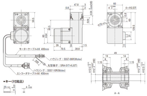
Parallel shaft gear head GFS gear · 60W
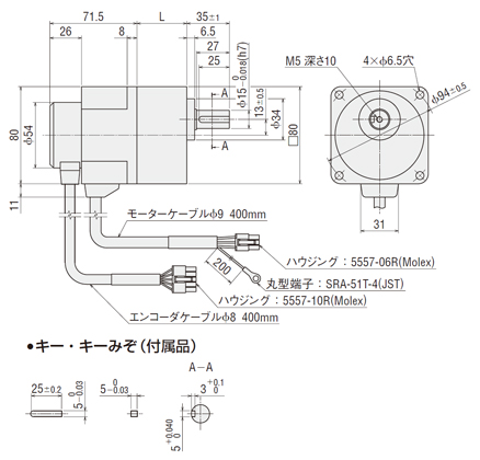
Hollow shaft flat gearhead FR gear · 60W
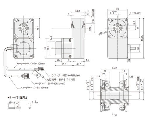
Parallel shaft gear head GFS gear · 120W
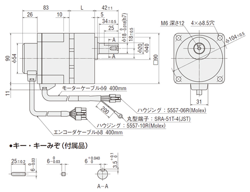
Hollow shaft flat gearhead FR gear · 120W
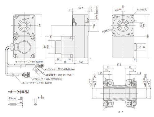
Parallel shaft gear head GFS gear · 200W · 400W
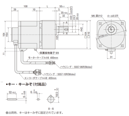
Hollow shaft flat gearhead FR gear · 200W · 400W
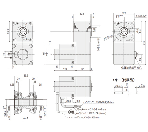
Parallel shaft gear head GFS gear L dimension / weight
| Motor product name | Gear head product name | Reduction ratio | L dimension | Weight (kg) | |
| Motor | Gear head | ||||
| BXM230-GFS | GFS2G□ | 5, 10, 15, 20 | 34 | 0.7 | 0.28 |
| 30, 50, 100 | 38 | 0.33 | |||
| 200 | 43 | 0.38 | |||
| BXM230-GFS | GFS2G□ | 5, 10, 15, 20 | 41 | 1.0 | 0.67 |
| 30, 50, 100 | 46 | 0.79 | |||
| 200 | 51 | 0.89 | |||
| BXM230-GFS | GFS2G□ | 5, 10, 15, 20 | 45 | 1.6 | 0.95 |
| 30, 50, 100 | 58 | 1.3 | |||
| 200 | 64 | 1.4 | |||
| BXM230-GFS | GFS2G□ | 5, 10, 15, 20 | 60 | 2.5 | 1.9 |
| 30, 50 | 72 | 2.4 | |||
| 100,200 | 86 | 3.0 | |||
Hollow shaft gearhead FR gear weight
| Motor product name | Gear head product name | Reduction ratio | Weight (kg) | |
| Motor | Gear head | |||
| BXM230-GFS | GFS2G□FR | 5, 10, 15, 20 | 0.7 | 0.8 |
| 30, 50, 100 | ||||
| 200 | ||||
| BXM230-GFS | GFS2G□FR | 5, 10, 15, 20 | 1.0 | 1.6 |
| 30, 50, 100 | ||||
| 200 | ||||
| BXM230-GFS | GFS2G□FR | 5, 10, 15, 20 | 1.6 | 2.2 |
| 30, 50, 100 | ||||
| 200 | ||||
| BXM230-GFS | GFS2G□FR | 5, 10, 15, 20 | 2.5 | 4.8 |
| 30, 50, 100 | ||||
| 200 | ||||
Driver (common to all models) external shape diagram
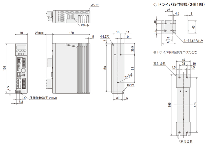
Specifications Table
Parallel shaft gear head GFS gear 30W, 60W, 120W
| Product Name | Motor/ | BXM230-* | BXM460-* | BXM5120-* | ||||
| Gear head | With Electromagnetic Brake | BXM230M-□ | BXM460M-□ | BXM5120M-□ | ||||
| Driver | BXSD30-A2 | BXSD30-C2 | BXSD60-A2 | BXSD60-C2 | BXSD120-A2 | BXSD120-C2 | ||
| Rated Output (Continuous) | W | 30 | 60 | 120 | ||||
| Power supply input | Rated Voltage | V | Single-phase 100-120 | Single-phase 200-240/ Three-phase 200-240 | Single-phase 100-120 | Single-phase 200-240/ Three-phase 200-240 | Single-phase 100-120 | Single-phase 200-240/ Three-phase 200-240 |
| Allowable Voltage Variation Range | -15 to +10% | -15 to +10% | -15 to +10% | |||||
| Frequency | Hz | 50/60 (Hz) | 50/60 (Hz) | 50/60 (Hz) | ||||
| Allowable Range of Frequency | ±5% | ±5% | ±5% | |||||
| Rated input current | A | 1.4 | Single-phase: 0.8/ Three-phase: 0.5 | 2.2 | Single-phase: 1.4/ Three-phase: 0.7 | 3.7 | Single-phase: 2.3/ Three-phase: 1.1 | |
| Maximum Input Current | A | 4.0 | Single-phase: 2.2/ Three-phase: 1.3 | 5.5 | Single-phase: 3.0/ Three-phase: 1.9 | 9.8 | Single-phase: 5.5/ Three-phase: 3.4 | |
| Rated Rotational Speed | [r/min] | 3000 | ||||||
| Speed Control Range* 1 | Digital setting: 2 to 4000 [r/min] (speed ratio 1:2000) Analog setting: 30 to 4000 [r/min] (speed ratio 1:133) | |||||||
| Against Load | ±0.05% or less: Conditions: 0 to rated torque, rated rotational speed, rated voltage, normal temperature | |||||||
| Compatible voltage | ±0.05% or less under the following conditions: -15 to +10% of rated voltage, rated rotating speed, no load, normal temperature | |||||||
| Compatible temperature | ±0.05% (±0.5%)* 2 or less under the following conditions: operating temperature range 0 to +50°C, rated rotating speed, no load, rated voltage | |||||||
| Electromagnetic brake* 2 | Type | Non-excitation type, automatic control by driver | ||||||
| Static friction torque | N⋅m | 0.1 | 0.2 | 0.4 | ||||
| Winding Operation Capability * 4 | Continuous regenerative power | W | 100 | |||||
| Instantaneous regenerative power | W | 240 | ||||||
| Compatible Regenerative Resistor | EPRC-400P (sold separately) | |||||||
✽ 2 Specifications when using analog settings.
✽ 3 Specifications for models with electromagnetic brake only. Starting and stopping by turning the power ON/OFF will cause abnormal wear of the electromagnetic brake. Do not perform this operation.
✽ 4 These values are for use with a regenerative resistor. Install the regenerative resistor in a location that has the same heat dissipation capacity as a heat sink (material: aluminum 350 x 350 mm with a thickness of 3 mm).
[ ! ] The values for each specification and characteristic are the characteristics of the motor alone.
[ ! ] A numeral in the square * of product names represents the reduction ratio.
| Reduction ratio | 5 | 10 | 15 | 20 | 30 | 50 | 100 | 200 | |||
| Rotational Direction | 30W, 60W, 120W | Same direction as the motor | Reverse to the motor | Same direction as the motor | |||||||
| Output Shaft Rotational Speed [r/min]* 1 | 2 r/min | 0.4 | 0.2 | 0.13 | 0.1 | 0.07 | 0.04 | 0.02 | 0.01 | ||
| 30 r/min | 6 | 3 | 2 | 1.5 | 1 | 0.6 | 0.3 | 0.15 | |||
| 3,000 r/min | 600 | 300 | 200 | 150 | 100 | 60 | 30 | 15 | |||
| 4,000 r/min | 800 | 400 | 267 | 200 | 133 | 80 | 40 | 20 | |||
| Allowable torque [N⋅m] | 30W | At 2 to 3,000 r/min | 0.45 | 0.9 | 1.4 | 1.8 | 2.6 | 4.3 | 6 | 6 | |
| At 4,000 r/min | 0.34 | 0.68 | 1 | 1.4 | 1.9 | 3.2 | 5.4 | 5.4 | |||
| 60W | At 2 to 3,000 r/min | 0.9 | 1.8 | .2.7 | 3.6 | 5.2 | 8.6 | 16 | 16 | ||
| At 4,000 r/min | 0.68 | 1.4 | 2 | 2.7 | 3.9 | 6.5 | 12.9 | 14 | |||
| 120W | At 2 to 3,000 r/min | 1.8 | 3.6 | 5.4 | 7.2 | 10.3 | 17.2 | 30 | 30 | ||
| At 4,000 r/min | 1.4 | 2.7 | 4.1 | 5.4 | 7.7 | 12.9 | 25.8 | 27 | |||
| Instantaneous maximum torque [N⋅m] | 30W | 0.9 | 1.8 | 2.7 | 3.6 | 5.2 | 8 | ||||
| 60W | 1.8 | 3.6 | 5.4 | 7.2 | 10.3 | 17.2 | 20 | ||||
| 120W | 3.6 | 7.2 | 10.8 | 14.4 | 20.6 | 34.4 | 40 | ||||
| Allowable radial load [N] | From output shaft tip 10 mm | 30W | At 2 to 3,000 r/min | 100 | 150 | 200 | |||||
| At 4,000 r/min | 90 | 130 | 180 | ||||||||
| 60W | At 2 to 3,000 r/min | 200 | 300 | 450 | |||||||
| At 4,000 r/min | 180 | 270 | 420 | ||||||||
| 120W | At 2 to 3,000 r/min | 300 | 400 | 500 | |||||||
| At 4,000 r/min | 230 | 370 | 450 | ||||||||
| From output shaft tip 20 mm | 30W | At 2 to 3,000 r/min | 150 | 200 | 300 | ||||||
| At 4,000 r/min | 110 | 170 | 230 | ||||||||
| 60W | At 2 to 3,000 r/min | 250 | 350 | 550 | |||||||
| At 4,000 r/min | 220 | 330 | 500 | ||||||||
| 120W | At 2 to 3,000 r/min | 400 | 500 | 650 | |||||||
| At 4,000 r/min | 300 | 430 | 550 | ||||||||
| Allowable axial load [N] | 30W | 40 | |||||||||
| 60W | 100 | ||||||||||
| 120W | 150 | ||||||||||
| Allowable Load Moment of Inertia J [×10-4kg·m2]* 2 | 30W | 12 (24) | 50 (100) | 110 (220) | 200 (400) | 370 (740) | 920 (1,840) | 2500 (3,750) | 5000 (7,500) | ||
| 60W | 22 (44) | 95 (190) | 220 (440) | 350 (700) | 800 (1600) | 2200 (4400) | 6200 (9300) | 12000 (18000) | |||
| 120W | 45 (90) | 190 (380) | 420 (840) | 700 (1400) | 1600 (3200) | 4500 (9000) | 12000 (18000) | 25000 (37500) | |||
| At instantaneous stop, [During instantaneous forward/reverse operation]* 3 | 30W | 1.55 | 6.2 | 14 | 24.8 | 55.8 | 155 | ||||
| 60W | 5.5 | 22 | 49.5 | 88 | 198 | 550 | |||||
| 120W | 25 | 100 | 225 | 400 | 900 | 2500 | |||||
✽ 2 When the rotating speed is 3000 r/min or less and the acceleration/deceleration time is 0.4 seconds or more, the permissible moment of inertia is the value shown in ( ).
Depending on the load conditions, we recommend using the regenerative resistor EPRC-400P (sold separately).
✽ 3 This also applies when the deceleration time is set to less than 0.1 seconds in digital settings.
Parallel shaft gear head GFS gear 200W, 400W
| Product Name | Motor/ | BXM6200-□ | BXM6400-□ | ||
| Gear head | With Electromagnetic Brake | BXM6200M-□ | BXM6400M-□ | ||
| Driver | BXSD200-A2 | BXSD200-C2 | BXSD400-C2 | ||
| Rated Output (Continuous) | W | 200 | 400 | ||
| Power supply input | Rated Voltage | V | Single-phase 100-120 | Single-phase 200-240/ Three-phase 200-240 | Single-phase 200-240/ Three-phase 200-240 |
| Allowable Voltage Variation Range | -15 to +10% | -15 to +10% | |||
| Frequency | Hz | 50/60 (Hz) | 50/60 (Hz) | ||
| Allowable Range of Frequency | ±5% | ±5% | |||
| Rated input current | A | 4.7 | Single-phase: 2.8/ Three-phase: 1.7 | Single-phase: 4.7/ Three-phase: 2.5 | |
| Maximum Input Current | A | 11.3 | Single-phase: 7.1/ Three-phase: 4.5 | Single-phase: 9.8/ Three-phase: 6.4 | |
| Rated Rotational Speed | [r/min] | 3000 | |||
| Speed Control Range* 1 | Digital setting: 2 to 4000 [r/min] (speed ratio 1:2000) Analog setting: 30 to 4000 [r/min] (speed ratio 1:133) | ||||
| Against Load | ±0.05% or less: Conditions: 0 to rated torque, rated rotational speed, rated voltage, normal temperature | ||||
| Compatible voltage | ±0.05% or less under the following conditions: -15 to +10% of rated voltage, rated rotating speed, no load, normal temperature | ||||
| Compatible temperature | ±0.05% (±0.5%)* 2 or less under the following conditions: operating temperature range 0 to +50°C, rated rotating speed, no load, rated voltage | ||||
| Electromagnetic brake* 2 | Type | Non-excitation type, automatic control by driver | |||
| Static friction torque | N⋅m | 0.65 | 1.3 | ||
| Winding Operation Capability * 4 | Continuous regenerative power | W | 100 | ||
| Instantaneous regenerative power | W | 800 | |||
| Compatible Regenerative Resistor | RGB100 (sold separately) | ||||
✽ 2 Specifications when using analog settings.
✽ 3 Specifications for models with electromagnetic brake only. Starting and stopping by turning the power ON/OFF will cause abnormal wear of the electromagnetic brake. Do not perform this operation.
✽ 4 These values are for use with a regenerative resistor. Install the regenerative resistor in a location that has the same heat dissipation capacity as a heat sink (material: aluminum 350 x 350 mm with a thickness of 3 mm).
[ ! ] The values for each specification and characteristic are the characteristics of the motor alone.
[ ! ] A numeral in the square * of product names represents the reduction ratio.
| Reduction ratio | 5 | 10 | 15 | 20 | 30 | 50 | 100 | 200 | |||
| Rotational Direction | 200W, 400W | Same direction as the motor | Reverse to the motor | Same direction as the motor | |||||||
| Output Shaft Rotational Speed [r/min]* 1 | 2 r/min | 0.4 | 0.2 | 0.13 | 0.1 | 0.07 | 0.04 | 0.02 | 0.01 | ||
| 30 r/min | 6 | 3 | 2 | 1.5 | 1 | 0.6 | 0.3 | 0.15 | |||
| 3,000 r/min | 600 | 300 | 200 | 150 | 100 | 60 | 30 | 15 | |||
| 4,000 r/min | 800 | 400 | 267 | 200 | 133 | 80 | 40 | 20 | |||
| Allowable torque [N⋅m] | 200W | At 2 to 3,000 r/min | 2.9 | 5.9 | 8.8 | 11.7 | 16.8 | 28 | 52.7 | 70 | |
| At 4,000 r/min | 2.2 | 4.3 | 6.5 | 8.6 | 12.4 | 20.6 | 38.9 | 63 | |||
| 400W | At 2 to 3,000 r/min | 5.9 | 11.7 | 17.6 | 23.4 | 33.5 | 55.9 | 70 | 70 | ||
| At 4,000 r/min | 4.3 | 8.6 | 12.8 | 17.1 | 24.5 | 40.9 | 63 | 63 | |||
| Instantaneous maximum torque [N⋅m] | 200W | 5.9 | 11.7 | 17.6 | 23.4 | 33.5 | 55.9 | 100 | 100 | ||
| 400W | 11.7 | 23.4 | 35.1 | 45 | 67.1 | 85 | 100 | 100 | |||
| Allowable radial load [N] | From output shaft tip 10 mm | 200W 400W | At 2 to 3,000 r/min | 550 | 1000 | 1400 | |||||
| At 4,000 r/min | 500 | 900 | 1200 | ||||||||
| From output shaft tip 20 mm | 200W 400W | At 2 to 3,000 r/min | 800 | 1250 | 1700 | ||||||
| At 4,000 r/min | 700 | 1100 | 1400 | ||||||||
| Allowable axial load [N] | 200W | 200 | 300 | 400 | |||||||
| 400W | |||||||||||
| Allowable Load Moment of Inertia J [×10-4 kg·m2]* 2 | 200W 400W | 100 (200) | 460 (920) | 1000 (2000) | 1700 (3400) | 3900 (7800) | 9300 (18600) | 18000 (36000) | 37000 (74000) | ||
| At instantaneous stop, [During instantaneous forward/reverse operation]* 3 | 200W | 50 | 200 | 450 | 800 | 1800 | 5000 | ||||
| 400W | |||||||||||
✽ 2 When the rotating speed is 3000 r/min or less and the acceleration/deceleration time is 0.4 seconds or more, the permissible moment of inertia is the value shown in ( ).
Depending on the load conditions, we recommend using the regenerative resistor EPRC-400P (sold separately).
✽ 3 This also applies when the deceleration time is set to less than 0.1 seconds in digital settings.
About vertical drive (winding operation)
trol even during winding operation.
During vertical drive (winding operation) as shown in the figure on the right, the motor is usually rotated by an external force and works as a power generator.
If that energy is applied to the driver,
it may cause a malfunction.
By using a regenerative resistor (sold separately),
the regenerative energy can be released as heat energy. When performing vertical drive or rapid
braking of large inertia, please use a regenerative resistor.
| Regenerative resistor model name (sold separately) | Compatible Products | Continuous regenerative power | Instantaneous regenerative power |
| EPRC-400P | BXSD30-A2, BXSD30-C2 | 100W | 240W |
| BXSD60-A2, BXSD60-C2 | |||
| BXSD120-A2, BXSD120-C2 | |||
| RGB100 | BXSD200-A2, BXSD200-C2 | 100W | 800W |
| BXSD400-C2 |
[ ! ] About regenerative power
Regenerative power can be estimated using the following formula, so please use it as a reference.
Regenerative power (W) = 0.1047 × TL [N⋅m] × N [r/min]
TL: load torque N: rotating speed
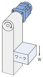
Winding Operation Capability
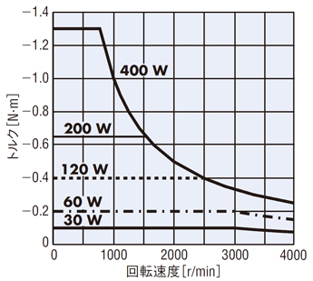
[ ! ] If continuous winding operation exceeding the continuous regenerative region is performed, the built-in thermostat (150°C) in the regenerative resistor will activate.
[ ! ] For lowering operation, please use the type with an electromagnetic brake.
Driver Specifications (Common)
| Items | Velocity Control Mode | Position Control Mode |
| Input signal | Photo Coupler Input: Input Resistance 6.6 kΩ Operates with internal power supply: 5 V DC Connectable external power supply: 24 V DC -15∼+20%, 100 mA or more Sink input/source input supported via external wiring | |
| Signals can arbitrary be assigned to any input port of IN0 to IN8 (9 points) [ ] Initial setting [FWD], [RVS], [M0], [M1], [M2], M3, [FREE], [STOP], [ALM-RST] TH, TL, S-ON, HMI, [Unused] | Signals can arbitrary be assigned to any input port of IN0 to IN8 (9 points) [ ] Initial setting [START], [M0], [M1], [M2], M3, [FREE], [STOP], [ALM-RST], [HOME] [HOMES], TH, SSTART, MS0, MS1, MS2, MS3, MS4, MS5, FWD, RVS, +JOG, -JOG, S-ON, P-PRESET, TL, HMI, Unused | |
| Output Signal | Photocoupler open collector output External power supply: 4.5 to 30 V DC, 100 mA or less Sinking output / sourcing output: Supplied through external wiring | |
| Signals can arbitrary be assigned to any output port of OUT0 to OUT2 (3 points) [ ] Initial setting [ALM], [WNG], [MOVE], END, TLC, VA, ZSG | Signals can arbitrary be assigned to any output port of OUT0 to OUT2 (3 points) [ ] Initial setting [ALM], WNG, MOVE, [READY], [HOME-P], END, TLC, VA, ZSG | |
| Transistor open collector output External power supply: DC4.5–30 V, 20 mA or less | ||
| ASG, BSG 500 pulses/1 rotating | ||
| Protective function | When one of the following protective functions is activated, the ALM output is turned OFF, and the motor stops. At the same time, the alarm code is displayed on the operation panel. Excessive position deviation✽, overcurrent, overvoltage, undervoltage, sensor error, main circuit output error, overload, overspeed, EEPROM error, initial sensor error, initial operation prohibition, regenerative resistor overheat, software overtravel✽, operation data error✽ | |
| Maximum Extension Distance | Between motor and driver: 30.7 m (using connection cable sold separately) | |
| Rated time | Continuous | |
Velocity Control Mode Specifications
| Items | Digital setting | Analog setting |
| Velocity Control Range | 2 to 4,000 r/min (settable in increments of 1 r/min) | 30 to 4,000 r/min |
| Speed setting method | Set using one of the following methods. · Operation panel · MEXE02✽1 · OPX-2A (sold separately) | Set using one of the following methods. (For operation data No. 2 to 15, only digital setting is available) · Operation data No. 0: Internal speed setting device (SPEED) · Operation data No. 1: External speed setting device or external DC voltage DC 0 to 10 V✽2 (1 mA or more) for external analog setting |
| Acceleration/deceleration time | 0.000–30.00 s (rating rotating speed, at no load) | 0.1–30 s (rating rotating speed, at no load) |
| Acceleration/deceleration time setting method | Set using one of the following methods. (Individual setting) · Operation panel · MEXE02✽1 · OPX-2A (sold separately) | The acceleration time and deceleration time are common to operation data No.0 and No.1. · Acceleration time setting device (ACC) · Deceleration time setting device (DEC) |
| Torque Limit Setting Range | 0–250% | |
| Torque Limit Setting Method | Set using one of the following methods. · Operation panel · MEXE02✽1 · OPX-2A (sold separately) | Torque limitation is common to all operation data · External speed setting device or external DC voltage DC 0–10 V✽2 (1 mA or more) via external analog setting |
| Number of operation data settings | 16 points | |
| Operation when the motor is stopped | Selectable operation when the motor is stopped · Motor de-energized (default setting) / · Servo lock stop (motor energized) | |
| Other operation | JOG operation, test operation, teaching (excluding MEXE02✽1) | |
When using MEXE02, a CC05IF-USB communication cable for support software (sold separately) is required. MISUMI does not handle this product.
✽ 2 The maximum voltage can be freely changed by parameter. Example: DC0∼5 V
Position Control Mode Specifications
| Items | Digital setting | |
| Positioning Operation | Travel length setting range | -8,388,608 to +8,388,607 steps |
| Resolution | 0.72° (500 steps/1 rotating) | |
| Speed setting range | 2 to 4,000 r/min (settable in increments of 1 r/min) | |
| Operation method | Incremental or absolute | |
| Operation function | Single, linked, linked 2, sequential, direct | |
| Acceleration/deceleration time | 0.000 to 30.00 s (rating rotating speed, at no load) | |
| Torque Limit Setting Range | 0–250% | |
| Number of operation data settings | 16 points | |
| How to set operation data | Set using one of the following methods. · Operation panel · MEXE02✽ · OPX-2A (sold separately) (Only torque limit can also be set by external analog input) | |
| Other operation | Continuous operation, JOG operation, homing operation, test operation, teaching | |
When using MEXE02, a CC05IF-USB communication cable for support software (sold separately) is required. MISUMI does not handle this product.
✽ 2 The maximum voltage can be freely changed by parameter. Example: DC0∼5 V
Position Control Mode Specifications
| Items | Specifications |
| Torque Limit Command | Depends on one of the following. · Digital individual setting: Set the torque limit value individually for each of the 16 data items. · External analog batch setting: Arbitrary setting using an external speed setting device or external DC voltage (DC0∼10 V✽1). The same torque limit value is set for all data. |
| Torque limit setting range* 2 | When the motor's rated torque value is considered 100%, the torque limit value can be set within the following range. · Digital setting: 0–250% (set in 1% increments) · External analog setting: 0–250% using an external speed setting device or external DC voltage (DC0–10 V✽1) |
✽ 2 Do not apply a load that exceeds the instantaneous maximum torque. .
[ ! ] Depending on the set speed, power supply voltage, and motor cable extension distance, a maximum error of approximately ±10% may occur between the set value and the generated torque (at rated torque and rated speed).
General Specifications
| Items | Motor | Driver | |
| Insulation resistance | After continuous operation at normal temperature and humidity, the value measured with a 500 V DC ohmmeter between the coil and case is 100 MΩ or more. (excluding the encoder) | After continuous operation at normal temperature and humidity, the value measured with a 500 V DC ohmmeter between the power supply terminal and protective earth terminal, and between the power supply terminal and input/output signal terminal is 100 MΩ or more. | |
| Dielectric strength | After continuous operation at normal temperature and humidity, no abnormality is observed even if 1.5 kV AC at 50 Hz is applied between the coil and case for 1 minute. (excluding the encoder) | After continuous operation at normal temperature and humidity, no abnormality is observed even if 1.5 kV AC at 50 Hz is applied for 1 minute between the power supply terminal and protective earth terminal, and 1.5 kV AC at 50 Hz is applied for 1 minute between the power supply terminal and input/output signal terminal. | |
| Temperature rise | The temperature rise in the coil is 50°C or lower and that in the case surface is 40°C or lower✽1 when measured by the thermocouple method after rated continuous operation under normal temperature and humidity. | After rated continuous operation at normal temperature and humidity, the temperature rise of the heat sink measured by the thermocouple method is 50°C or less. (60°C or less when mounted in close contact for 200 W and 400 W types) | |
| Operating environment* 2 | Ambient temperature | 0 to +50°C (No freezing) | 0 to +50°C (No freezing)✽2 For 200 W and 400 W types with close contact mounting, 0 to +40°C |
| Ambient humidity | 85% or less (No condensation) | ||
| Altitude | 1,000 m or Less above sea level | ||
| Environment | No corrosive gases or dust. Cannot be used in a special environment such as radioactive area, magnetic field, and vacuum. | ||
| Vibration | No continuous vibration or excessive shock should be applied. Conforms to JIS C60068-2-6 "Sine-wave vibration test method". Frequency Range: 10 to 55 Hz, Half amplitude: 0.15 mm, Sweep Direction: 3-direction (X, Y, Z), Number of sweeps: 20 times | ||
| Storage Environment* 3 | Ambient temperature | -20 to +60°C (No freezing) | -25 to +70°C (No freezing) |
| Ambient humidity | 85% or less (No condensation) | ||
| Altitude | Altitude: 3,000 m or less | ||
| Environment | No corrosive gases or dust. No direct contact with water or oil. Cannot be used in a special environment such as radioactive area, magnetic field, and vacuum. | ||
| Heat-resistant class | UL/CSA standard: 105 (A); EN standard: 120 (E) | - | |
| Protection Rating | IP54 (excluding the mounting surface and connector section of the round shaft type) | IP20 | |
30 W type: 115×115 mm, thickness 5 mm; 60 W type: 135×135 mm, thickness 5 mm; 120 W type: 165×165 mm, thickness 5 mm
200 W type: 200×200 mm, thickness 5 mm; 400 W type: 250×250 mm, thickness 6 mm
✽ 2 Please install the driver in a location with heat dissipation capability equivalent to an aluminum metal plate.
Individual installation: 200×200 mm, thickness 2 mm
Tight installation: 350×350 mm, thickness 2 mm
For 200 W and 400 W types: When using the driver rail mount bracket or DIN rail mount bracket (sold separately), keep the load factor at 90% or less.
✽ 3 The storage environment values are for short periods, including during transportation.
[ N/A ] Do not perform insulation resistance measurement or withstand voltage test while the motor and driver are connected.
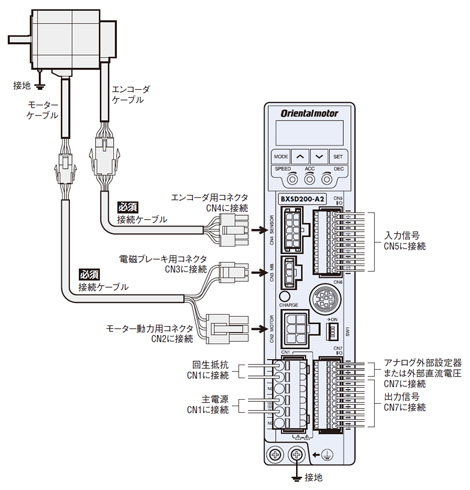
Connection Cable and Combination List
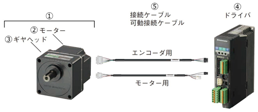
[ ! ] The maximum extension distance between the motor and driver is 30.7 m.
[ ! ] Please make sure to purchase either a connection cable or a flexible connection cable. Both connection cable and flexible connection cable come as a set of two cables: one for the motor and one for the encoder. .
| Output | Type | Motor unit | Driver | Connection Cable (sold separately) Flexible Connection Cable (sold separately) | ||
| Product Name | Motor (single item) | Gearhead (single item) | ||||
| (1) | (2) | (3) | (4) | (5) | ||
| 30 W | parallel shaft gear head GFS gear | BXM230■-□ | BXM230■-GFS | GFS2G□ | BXSD30-A2 BXSD30-C2 | CC◇SBF2 CC◇SBR2 |
| Hollow shaft flat gearhead FR gear | BXM230■-□FR | BXM230■-GFS | GFS2G□FR | |||
| Round shaft type *1 | BXM230■-A2 | BXM230■-A2 | - | |||
| 60 W | parallel shaft gear head GFS gear | BXM460■-□ | BXM460■-GFS | GFS4G□ | BXSD60-A2 BXSD60-C2 | CC◇SBF2 CC◇SBR2 |
| Hollow shaft flat gearhead FR gear | BXM460■-□FR | BXM460■-GFS | GFS4G□FR | |||
| Round shaft type *1 | BXM460■-A2 | BXM460■-A2 | - | |||
| 120 W | parallel shaft gear head GFS gear | BXM5120■-□ | BXM5120■-GFS | GFS5G□ | BXSD120-A2 BXSD120-C2 | CC◇SBF2 CC◇SBR2 |
| Hollow shaft flat gearhead FR gear | BXM5120■-□FR | BXM5120■-GFS | GFS5G□FR | |||
| Round shaft type *1 | BXM5120■-A2 | BXM5120■-A2 | - | |||
| 200 W | parallel shaft gear head GFS gear | BXM6200■-□ | BXM6200■-GFS | GFS6G□ | BXSD200-A2 BXSD200-C2 | CC◇SBF2 CC◇SBR2 |
| Hollow shaft flat gearhead FR gear | BXM6200■-□FR | BXM6200■-GFS | GFS6G□FR | |||
| Round shaft type *1 | BXM6200■-A | BXM6200■-A | - | |||
| 400 W | parallel shaft gear head GFS gear | BXM6400■-□ | BXM6400■-GFS | GFS6G□ | BXSD400-C2 | CC◇SBF2 CC◇SBR2 |
| Hollow shaft flat gearhead FR gear | BXM6400■-□FR | BXM6400■-GFS | GFS6G□FR | |||
| Round shaft type *1 | BXM6400■-A | BXM6400■-A | - | |||
[ ! ] For motors with an electromagnetic brake, an M will appear in the ■ of the product name.
[ ! ] A numeral in the square * of product names represents the reduction ratio.
[ ! ] A numeral in the square ◇ of product names represents the cable length.
Part Names and Functions of Each Driver
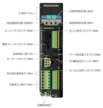
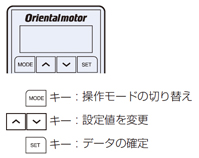 | Operating mode | Detail | |
| Velocity Control | Position Control | ||
| Monitor | Velocity, load factor, operation number, alarm code, warning code, I/O monitor, control mode | Velocity, position, load factor, operation number, selection number, alarm code, warning code, I/O monitor, control mode | |
| Data | Data No. 0–15 (16 points) Operating speed, torque limit, acceleration time, deceleration time, data clear | Data No. 0–15 (16 points) Operation method, position, operating speed, operating function, sequential positioning, torque limit, acceleration time, deceleration time, data clear | |
| Parameter | Set various parameters | ||
| Test | I/O test, JOG operation, data No. selection operation, teaching | I/O test, JOG operation, data No. selection operation, home return operation, position preset, teaching | |
| No. | function |  | ||
| 1 | Switching between Velocity Control Mode and Position Control Mode ON: Position Control Mode OFF: Velocity Control Mode | Factory setting: OFF | ||
| 2 | BX Compatibility Mode setting When set to ON, the input/output signals and content will match those of the BX series. | Factory default: OF | ||
| 3 | Unused | |||
| 4 | Select the power supply for input signals (built-in or external) | Factory setting: OFF (external) | ||
| pin No. | Signal Name | function | |
| 1 | IN-COM0 | input signal common (for external power supply) | |
| 2 | IN0 | FWD | Rotating in the FWD direction / Deceleration stop |
| 3 | IN1 | RVS | Rotating in the RVS direction / Decelerate and stop |
| 4 | IN2 | M0 | Operation data No. selection |
| 5 | IN3 | M1 | |
| 6 | IN4 | M2 | |
| 7 | IN5 | FREE | Release of motor excitation, release of electromagnetic brake |
| 8 | IN6 | STOP | Instant stop when input during motor operation |
| 9 | IN7 | ALM-RST | Alarm release |
| 10 | IN8 | Not used (functionality can be expanded) | |
| 11 | IN-COM1 | 0 V (for internal power supply) | |
| pin No. | Signal Name | function | |
| 1 | IN-COM0 | input signal common (for external power supply) | |
| 2 | IN0 | HOME | Start homing operation |
| 3 | IN1 | START | Positioning Operation Start |
| 4 | IN2 | M0 | Operation data No. selection |
| 5 | IN3 | M1 | |
| 6 | IN4 | M2 | |
| 7 | IN5 | FREE | Release of motor excitation, release of electromagnetic brake |
| 8 | IN6 | STOP | Instant stop when input during motor operation |
| 9 | IN7 | ALM-RST | Alarm release |
| 10 | IN8 | HOMES | Machine origin sensor |
| 11 | IN-COM1 | 0 V (for internal power supply) | |
| pin No. | Signal Name | function | |
| 1 | VH | Analog external setting input Connect when controlling with an external speed setting device or external direct current voltage. | |
| 2 | VM | ||
| 3 | VL | ||
| 4 | OUT0+ | ALM | Output when an alarm occurs |
| 5 | OUT0- | ||
| 6 | OUT1+ | MOVE | Output during motor operation |
| 7 | OUT1- | ||
| 8 | OUT2+ | WNG | Output when a warning occurs |
| 9 | OUT2- | ||
| 10 | ASG | A phase output | |
| 11 | BSG | B phase output | |
| 12 | OUT-COM | Common for ASG/BSG | |
| pin No. | Signal Name | function | |
| 1 | VH | Analog external setting input Connect when controlling with an external speed setting device or external direct current voltage. | |
| 2 | VM | ||
| 3 | VL | ||
| 4 | OUT0+ | ALM | Output when an alarm occurs |
| 5 | OUT0- | ||
| 6 | OUT1+ | READY | Output when operation preparation is complete |
| 7 | OUT1- | ||
| 8 | OUT2+ | HOME-P | Output when origin detection occurs |
| 9 | OUT2- | ||
| 10 | ASG | A phase output | |
| 11 | BSG | B phase output | |
| 12 | OUT-COM | Common for ASG/BSG | |