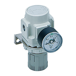
Direct-Operated Precision Regulator, Modular Type (With Backflow Function), ARP20(K) To ARP40(K) Series
Caution
- Refer to the catalog for details on product specifications.
- Product images may be representative. Refer to the manufacturer's catalog for details.
Product Description
Direct-Operated Precision Regulator, Modular Type (With Backflow Function) with sensitivity within 0.2% F.S.
[Features]
· Repeatability: Within ±1% F.S. (or within ±3 kPa).
· Energy saving and air consumption reduced by 80%.
· Type with the backflow function (ARP20K/30K/40K) can be installed between solenoid valves and cylinders.
· Specifications with a backflow function feature an inbuilt mechanism for quickly and reliable exhausting the air-pressure at the outlet side.
Direct-Operated Precision Regulator, Modular Type (With Backflow Function), ARP20(K) To ARP40(K) Series Details

ARP20/ARP20K: product images

ARP30/ARP30K: product images

ARP40/ARP40K: product images
Direct-Operated Precision Regulator, Modular Type (With Backflow Function), ARP20(K) To ARP40(K) Series Specification
Model Number Notation

Model number example
| - | Code | Contents | (1) | |||||
|---|---|---|---|---|---|---|---|---|
| Body size | ||||||||
| 20 | 30 | 40 | ||||||
| (2) | With backflow function | No symbol | Without backflow function | ● | ● | ● | ||
| K | With backflow function | ● | ● | ● | ||||
| (3) | Screw Type | No symbol | Rc | ● | ● | ● | ||
| N | NPT | ● | ● | ● | ||||
| F | G | ● | ● | ● | ||||
| (4) | Piping connection port diameter | 01 | 1/8 | ● | - | - | ||
| 02 | 1/4 | ● | ● | ● | ||||
| 03 | 3/8 | - | ● | ● | ||||
| 04 | 1/2 | - | - | ● | ||||
| (5) | Note 1) Options | a | Mounting | No symbol | Without optional mounting parts | ● | ● | ● |
| B Note 2) | With Bracket | ● | ● | ● | ||||
| H | With set nut (for panel mount) | ● | ● | ● | ||||
| b | Pressure gauge | No symbol | Without pressure gauge | ● | ● | ● | ||
| E | Square embedded-type pressure gauge (with limit indicator) | ● | ● | ● | ||||
| G | Round-type pressure gauge (with limit indicator) | ● | ● | ● | ||||
| Digital pressure switch | E1Note 3) | Output: NPN output / Lead wire electrical entry: wiring bottom entry | ● | ● | ● | |||
| E2Note 3) | Output: NPN output / Lead wire electrical entry: wiring top entry | ● | ● | ● | ||||
| E3Note 3) | Output: PNP output / Lead wire electrical entry: wiring bottom entry | ● | ● | ● | ||||
| E4Note 3) | Output: PNP output / Lead wire electrical entry: wiring top entry | ● | ● | ● | ||||
| (6) | Semi-standard | c | Set pressure | No symbol | 0.005 to 0.4-MPa setting | ● | ● | ● |
| 1 Note 4) | 0.005 to 0.2‑MPa setting | ● | ● | ● | ||||
| 3 Note 4) | 0.008 to 0.6-MPa setting | ● | ● | ● | ||||
| d | Flow direction | No symbol | Flow direction: left → right | ● | ● | ● | ||
| R | Flow direction: right → left | ● | ● | ● | ||||
| e | Handle direction | No symbol | Handle downward | ● | ● | ● | ||
| Y | Handle upward | ● | ● | ● | ||||
| f | Pressure unit | No symbol | Nameplate and pressure gauge units: MPa | ● | ● | ● | ||
| Z Note 5) | Nameplate and pressure gauge units: psi | ○ Note 7) | ○ Note 7) | ○ Note 7) | ||||
| ZA Note 6) | Digital pressure switch: with unit selection function | △ Note 8) | △ Note 8) | △ Note 8) | ||||
- *Note 1) Options B, G and H are not assembled and are supplied loose at the time of shipment.
- *Note 2) Set nuts are included with the bracket.
- *Note 3) When choosing with H (panel mount), the installation space for lead wires will not be secured. In this case, select "wiring top entry" for the electrical entry. (Select "wiring bottom entry" when the semi-standard Y is chosen simultaneously.)
- *Note 4) The pressure regulator spring is the only difference from the standard specification. Does not restrict setting to a pressure of 0.2 MPa / 0.6 MPa or higher. Moreover, if a pressure gauge is attached, a 0.2‑MPa-use pressure gauge for 0.2‑MPa settings will be fitted or a 0.7‑MPa‑use pressure gauge for 0.6 MPa settings. For all times when a digital pressure switch is attached, the pressure display is fixed to 1.0 MPa.
- *Note 5) Thread type: NPT is applicable. Under new Japanese measurement laws, this product is only available for sale outside of Japan (SI units are used in Japan). The digital pressure switch, which has the unit selection function, has a default setting of psi.
- *Note 6) Options: E1, E2, E3, E4. Under new Japanese measurement laws, this product is only available for sale outside of Japan (SI units are used in Japan).
- *Note 7) ○ is for thread type NPT only.
- *Note 8) △: Combination available for options E1, E2, E3, E4.
Specifications
| Model | ARP20(K) | ARP30(K) | ARP40(K) | ||
|---|---|---|---|---|---|
| Connection port size | 1/8, 1/4 | 1/4, 3/8 | 1/4, 3/8, 1/2 | ||
| Applicable fluids | Air | ||||
| Proof pressure | 1.2 MPa | ||||
| Maximum operating pressure | 0.7 MPa | ||||
| Set pressure range Note 1) | For 0.4‑MPa setting | Example: ARP30-02BG | 0.005 to 0.4 MPa | ||
| For 0.2‑MPa setting | Example) ARP30-02BG-1 | 0.005 to 0.2 MPa | |||
| For 0.6‑MPa setting | Example) ARP30-02BG-3 | 0.008 to 0.6 MPa | |||
| Sensitivity | Within 0.2% F.S. | ||||
| Repeatability Note 2) | Within ±1% F.S. (or ±3 kPa) | ||||
| Air consumption amount | For 0.4‑MPa setting | Example: ARP30-02BG | 1 L/min (ANR) or less (at P2 = 0.4 MPa) | ||
| For 0.2‑MPa setting | Example) ARP30-02BG-1 | 0.6 L/min (ANR) or less (at P2 = 0.2 MPa) | |||
| For 0.6‑MPa setting | Example) ARP30-02BG-3 | 1.4 L/min (ANR) or less (at P2 = 0.6 MPa) | |||
| Pressure connection port size Note 3) | 1/8 | 1/8 | 1/4 | ||
| Ambient temperature and working fluid temperature | - | -5 to 60°C (no freezing) | |||
| With Digital Pressure Switch | Example) ARP30-02BE1 | -5 to 50°C (no freezing) | |||
| Structure | Bleed type | ||||
| Weight (kg) Note 4) | 0.2 | 0.3 | 0.5 | ||
- *Note 1) When a product with the backflow function (ARP20K to 40K) is chosen, set the inlet pressure to at least 0.05‑MPa higher than the set pressure.
- *Note 2) For the type set to 0.2 MPa only, repeatability will be within ±3 kPa.
- *Note 3) Connection port threading is not provided for products with square embedded pressure gauges.
- *Note 4) The weight shown is for the product without any options.
Optional parts
| Model | ARP20(K) | ARP30(K) | ARP40(K) | ||
|---|---|---|---|---|---|
| Bracket assembly Note 1) | ARP20P-270AS | ARP30P-270AS | ARP40P-270AS | ||
| Set nut | AR23P-260S | AR33P-260S | AR43P-260S | ||
| Pressure gauge | 0.4 MPa | Round-type Note 2) | G36-4-□01 | G46-4-□02 | |
| Square embedded type Note 3) | GC3-4AS [GC3P-010AS (pressure gauge cover only)] | ||||
| 0.2 MPa | Round-type Note 2) | G36-2-□01 | G46-2-□02 | ||
| Square embedded type Note 3) | GC3-2AS [GC3P-010AS (pressure gauge cover only)] | ||||
| 0.7 MPa | Round-type Note 2) | G36-7-□01 | G46-7-□02 | ||
| Square embedded type Note 3) | GC3-7AS [GC3P-010AS (pressure gauge cover only)] | ||||
| Digital type Note 4) | NPN output / Wiring bottom entry | ISE35-N-25-MLA [ISE35-N-25-M (main switch unit only)] | |||
| NPN output / Wiring bottom entry | ISE35-R-25-MLA [ISE35-R-25-M (main switch unit only)] | ||||
| PNP output / Wiring bottom entry | ISE35-N-65-MLA [ISE35-N-65-M (main switch unit only)] | ||||
| PNP output / Wiring bottom entry | ISE35-R-65-MLA [ISE35-R-65-M (main switch unit only)] | ||||
- *Note 1) Assembly of a bracket and set nuts.
- *Note 2) The □ in the part numbers for round-type pressure gauges indicates the connection thread type. Insert no symbol for Rc thread, and use "N" for NPT thread. The G thread is not available. As such, select the R thread type (Nil) instead. Contact the manufacturer separately regarding NPT connection thread types and for psi unit specification pressure gauges.
- *Note 3) Including O-ring (1 pc.) and mounting screws (2 pcs.). [ ]: Pressure gauge cover only.
- *Note 4) Includes a lead wire with connector (2 m), adapter, lock pin, O-ring (1 pc.) and mounting screws (2 pcs.). [ ]: Switch unit only.
Structural Drawings

Direct-Operated Precision Regulator, Modular Type (With Backflow Function), ARP20(K) To ARP40(K) Series: structural drawings
Component Parts
| Number | Part name | Materials | Additional notes |
|---|---|---|---|
| 1 | Body | Die-cast aluminum | External color: urban white |
| 2 | Bonnet | Polyacetal | External color: urban white |
Replacement Parts
| Number | Part name | Materials | Part number | ||
|---|---|---|---|---|---|
| ARP20(K) | ARP30(K) | ARP40(K) | |||
| 3 | Valve assembly | Brass, HNBR, NBR | ARP20P-330AS | ARP30P-330AS | ARP40P-330AS |
| 4 | Valve guide assembly | Polyacetal, NBR | ARP20P-050AS | ARP30P-050AS | ARP40P-050AS |
| 5 | Diaphragm assembly | HNBR, SUS, brass | ARP20P-151AS | ARP30P-151AS | ARP40P-151AS |
| 6 Note) | Check valve assembly | - | AR20KP-020AS | ||
- *Note) The check valve assembly is a replacement part for specifications with the backflow function (ARP20K to 40K). Assembly comprising check valve body assembly, check valve cover and screws (2 pcs.).
Direct-Operated Precision Regulator, Modular Type (With Backflow Function), ARP20(K) To ARP40(K) Series Dimensions
(Unit: mm)

Direct-Operated Precision Regulator, Modular Type (With Backflow Function), ARP20(K) To ARP40(K) Series: dimensional drawing
Pressure Gauge Options
| Option | Square embedded type pressure gauge | Digital pressure switch (Electrical entry: wiring bottom entry) | Digital pressure switch (Electrical entry: wiring top entry) | Round-type pressure gauge |
|---|
| Model | Standard specification | ||||||||
|---|---|---|---|---|---|---|---|---|---|
| P1 | P2 | A | B Note 1) | C | D | F | J | K | |
| ARP20(K) | 1/8, 1/4 | 1/8 | 40 | 98 | 27 | 28.5 | M28 × 1 | 28.5 | 2 Note 2) |
| ARP30(K) | 1/4, 3/8 | 1/8 | 53 | 117 | 29 | 29.5 | M38 × 1.5 | 29.5 | 2.5 |
| ARP40(K) | 1/4, 3/8, 1/2 | 1/4 | 70 | 148 | 41 | 34 | M42 × 1.5 | 34 | 1 |
| Model | Option specification | ||||||||||||||||
|---|---|---|---|---|---|---|---|---|---|---|---|---|---|---|---|---|---|
| Square type pressure gauge | Digital pressure gauge | Round-type pressure gauge | Bracket mounting dimensions | Panel mount | |||||||||||||
| H | J | H | J | H | J | M | N | Q | R | S | T | U | V | W | Y | Z | |
| ARP20(K) | □28 | 29.5 | □27.8 | 40 | ø37.5 (diameter 37.5 mm) | 66 | 30 | 34 | 47 | 5.4 | 15.4 | 55 | 2.3 | 28 | 28.5 | 14 | 6 |
| ARP30(K) | □28 | 30.5 | □27.8 | 41 | ø37.5 (diameter 37.5 mm) | 67 | 41 | 40 | 44 | 6.5 | 8 | 53 | 2.3 | 31 | 38.5 | 19 | 7 |
| ARP40(K) | □28 | 35 | □27.8 | 45 | ø42.5 (diameter 42.5 mm) | 74 | 50 | 54 | 54 | 8.5 | 10.5 | 70 | 2.3 | 35.5 | 42.5 | 21 | 7 |
- *Note 1) The dimension B is the length when the filter regulator knob (handle) is unlocked.
- *Note 2) For the ARP20(K) only, the position of the pressure gauge is above the center of the piping.