Rectangular Miniature Multi-Pin Rack / Panel Crimp Connector, QR/P1 Series
Caution
Product Description
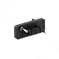
Compact, high-density mounted, rectangular multipole rack/panel plug-in connector QR/P. Compact crimp terminals divided into power supply and signal use.
[Features]
· The terminals have smooth insertion and removal feel, and stable contact pressure is achieved by point and blade contact, and there is some flexibility for the width corresponding to the variation in the connector connection length unique to the plug-in connection.
· The terminals are made compact by segregating according to those for power and those for signals.
· The housing internal pinout has pin 12 opposing pin 2 on one side, pins 8, 24 opposing pin 2 on both sides (total: 4 pins), and pin 32 opposing pin 3 on one side (total: 6 pins) with a greater distance of separation from other pins. These terminal pins feature a creepage distance that can adequately withstand high voltages. Therefore, the terminals can be used as power supply terminals.
· Additionally, a flame retardant material (UL9V-0) is used for the insulating material.
· Guide pins are metallic to withstand coupling impact.
· Installation to a panel or rack is achieved via a floating bush. Therefore, insertion and removal do not require the application of excessive force.
In-stock items are made-to-order, so returns and cancellations are not possible. Thank you for your understanding.
Small Rectangular Multi-Electrode Solderless Connector For Racks / Panels

QR/P1 Series
Specifications of QR/P1 Series Rack and Panel Connector
Product Standards
| QR/P1 Safety Standard Certification Ratings | |||||||
|---|---|---|---|---|---|---|---|
| Safety Standards | UL | CSA | TÜV | ||||
| Operating Temperature Range | -10 to +60°C | ||||||
| Rated voltage | Power Supply Unit | 120 V AC | 250 V AC | 125 V AC | 250 V AC | 250 V AC, 300 V DC | |
| Signal part | 125 V AC, 150 V DC | ||||||
| Rated Current | AWG#14 | 10 A | 3 A | 10 A | 3 A | 10 A | |
| AWG#16 | 8 A | ||||||
| AWG#18 | 3 A | 1 A | 3 A | 1 A | 5 A | ||
| AWG#20 | 2.5 A | ||||||
| AWG#22 | 1 A | ||||||
| AWG #24 | Power Supply Unit | 2 A | 1 A | 2 A | 1 A | ||
| Signal part | 1 A | 0.5 A | 1 A | 0.5 A | |||
| AWG#26 | 1 A | 0.5 A | 1 A | 0.5 A | |||
| AWG#28 | – | ||||||
Materials/Processing
| Part Name | Materials | Color/Finish |
|---|---|---|
| Insulator | PBT resin* | Black |
| Contacts | Phosphor bronze | Nickel base Selective gold plating |
- *UL94V-0
Power Supply Contact Configuration
Male housing (diagram viewed from wiring side), "■" indicates a contact hole for the power supply

QR/P1-8P/C(51)

QR/P1-12P-C(51)

QR/P1-16P-C(51)

QR/P1-24P-C(51)

QR/P1-32P-C(51)
Product Outline Drawing And Dimensions
Housing

Male housing

Dimensional drawing

Female housing

Dimensional drawing
Contact

Male contact for power supply
Plating: nickel base and selective gold plating

Female contact for power supply
Plating: nickel base and selective gold plating

Male contact for signal
Plating: nickel base and selective gold plating

Female contact for signal
Plating: nickel base and selective gold plating
Panel mounting dimensional drawing (for S insulated case)

Mounting from rear of panel

Mounting from front of panel
Units: mm, Tolerance: ±0.2
| Symbol | 8-contacts | 12-contacts | 16-contacts | 24-contacts | 32-contacts | |
|---|---|---|---|---|---|---|
| Rear surface mounting | A | 36.9 | 42 | 48.1 | 59.3 | 76 |
| B | 29.4 | 34.5 | 40.6 | 51.8 | 68.5 | |
| C | 28.4 | 33.5 | 39.6 | 50.8 | 67.5 | |
| D | 4.3 | 3.3 | 4.3 | 4.3 | 4.3 | |
| Front surface mounting | E | 22.4 | 27.5 | 33.6 | 44.8 | 61 |
| F | 36.9 | 42 | 48.1 | 59.3 | 76 | |
| G | 4.3 | 3.3 | 4.3 | 4.3 | 4.3 | |
- *The panel mounting dimensions for the P insulation case are a mirror image of the mounting dimensions for the S insulated case in which the right and left sides are reversed.