Square Rack, Pressure Angle 20°, Length Configurable

Brand :
MISUMI
Caution
Product Description
Product Overview
Rack is often used together with gears and is a type of mechanical component used for transmission. Allows rotational displacement to be transmitted linearly, and linear displacement to be transmitted rotationally.
Gear rack drive mechanisms can be used in elevators, rail systems, automotive steering systems, machine tools, and actuator feed mechanisms, among other fields.
Gear rack drive mechanisms can be used in elevators, rail systems, automotive steering systems, machine tools, and actuator feed mechanisms, among other fields.
Dimensional Drawing


Material Table
| Type |  Material Material |  Surface Treatment Surface Treatment | |
| Designated hole position type | Designated number of holes type | ||
| E-RGSAL | E-LRGSA | Steel | Black Oxide Film |
| E-RGSASL | E-LRGSAS | Stainless Steel | - |
 This product series is processed on one end only. Please pay attention when selecting.The cut surface and hole-machined surface are not surface treated. Please note.This series of products is not heat treated. If needed, please select the high-frequency quenching series products.If rust prevention is required, please prioritize stainless steel products. For details, please refer to Rust Prevention Performance and Maintenance of Metal Materials and Their Surface Treatments.For the electronic catalog, please click here to get it
Alteration
| Alterations | Additional female thread machining on one end face | Additional female thread machining on both ends |
| Code | MC | WMC |
| Spec. |  |  |
Specification Table
● Specification Table
● Hole Position Specification Type
 For stainless steel material, please refer to the dimensions in ( )
● Designated number of holes type
This product series is processed on one end only. Please pay attention when selecting.
For stainless steel material, please refer to the dimensions in parentheses.
● Hole Position Specification Type
| Part Number | Overall length L can be specified down to 1 mm increments | Hole position ABCD can be specified down to 1 mm increments | P (Pitch) | W | H | h | M (Coarse Thread) | d1 | d2 | Z1 | ||
| Type | Module | Hole machining | ||||||||||
| E-RGSAL E-RGSASL | 1.0 | N(No hole machining) HT(Back side threaded hole) ST(Side threaded hole) Z(Side counterbore) | 20 to 980 | 5 to 975 | 3.142 | 17 (10) | 17 (10) | 16 (9) | M3 | 3.5 | 6.5 (6) | 3.5 |
| 1.5 | 4.712 | 17 (15) | 17 (15) | 15.5 (13.5) | M4 | 4.5 | 8 | 4.5 | ||||
| 2.0 | 6 to 974 | 6.283 | 24 (20) | 24 (20) | 22 (18) | M5 | 5.5 | 9.5 | 5.5 | |||
| 2.5 | 7.854 | 24 (25) | 24 (25) | 21.5 (22.5) | M5 | 5.5 | 9.5 | 5.5 | ||||
| 3.0 | 9.425 | 29 (30) | 29 (30) | 26 (27) | M5 | 5.5 | 9.5 | 5.5 | ||||
For stainless steel material, please refer to the dimensions in ( )● Designated number of holes type
| Part Number | Total Length L Specify 1 mm | K (Number of Holes) | Hole Pitch B can be specified down to 1 mm increments | P (Pitch) | W | H | h | M (Coarse Thread) | d1 | d2 | Z1 | ||
| Type | Module | Hole machining | |||||||||||
| E-LRGSA E-LRGSAS | 1.0 | HT(Back Threaded Hole) ST(Side Threaded Hole) Z(Side Counterbore) | 20 to 980 | 2 to 12 | 50 to 500 | 3.142 | 17 (10) | 17 (10) | 16 (9) | M3 | 3.5 | 6.5 (6) | 3.5 |
| 1.5 | 4.712 | 17 (15) | 17 (15) | 15.5 (13.5) | M4 | 4.5 | 8 | 4.5 | |||||
| 2.0 | 6.283 | 24 (20) | 24 (20) | 22 (18) | M5 | 5.5 | 9.5 | 5.5 | |||||
| 2.5 | 7.854 | 24 (25) | 24 (25) | 21.5 (22.5) | M5 | 5.5 | 9.5 | 5.5 | |||||
| 3.0 | 9.425 | 29 (30) | 29 (30) | 26 (27) | M5 | 5.5 | 9.5 | 5.5 | |||||
This product series is processed on one end only. Please pay attention when selecting.For stainless steel material, please refer to the dimensions in parentheses.Product Features
Feature 1: Can be converted between rotary motion and linear motion.
Feature 2: Length and mounting hole processing method can be specified.
Feature 3: You can choose between standard steel and stainless steel racks according to actual operating requirements.
Feature 4: The hole machining method can be freely selected: no hole machining, back side tapped hole machining, side counterbore machining, or side tapped hole machining.
Feature 5: Optimized cross-sectional shape, better suited for domestic usage environments
Feature 2: Length and mounting hole processing method can be specified.
Feature 3: You can choose between standard steel and stainless steel racks according to actual operating requirements.
Feature 4: The hole machining method can be freely selected: no hole machining, back side tapped hole machining, side counterbore machining, or side tapped hole machining.
Feature 5: Optimized cross-sectional shape, better suited for domestic usage environments
Usage Method
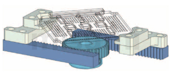
■ Linear Motion: Rack and Pinion Drive
Bracket Micro Gear Type Slide Table Assembly
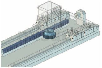
Positioning Mechanism for Basic Frame
Precautions
■ Cutting Method for Rack End Face
■ Rack Connection Method
The end face machining accuracy of MISUMI racks is less than the pitch.
Therefore, please leave a gap between the two racks as shown in the diagram below, and connect them after adjusting the pitch using a combination rack (racks with the same module).


■ Rack Connection Method
The end face machining accuracy of MISUMI racks is less than the pitch.
Therefore, please leave a gap between the two racks as shown in the diagram below, and connect them after adjusting the pitch using a combination rack (racks with the same module).

Example of Use


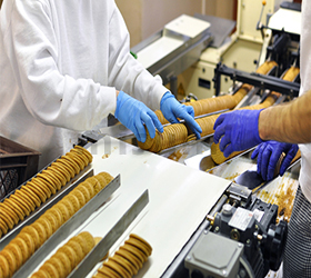
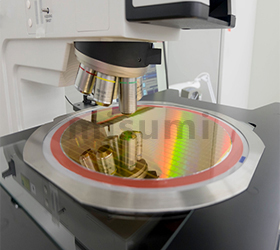
Application Industries
Related Products


Related Documents
For related information on gears, please refer to  Gear Technical Information
For information on metal materials and their surface treatment, please refer toRust Prevention and Maintenance of Metal Materials and Their Surface Treatment
Gear Technical InformationFor information on metal materials and their surface treatment, please refer to
Rust Prevention and Maintenance of Metal Materials and Their Surface Treatment