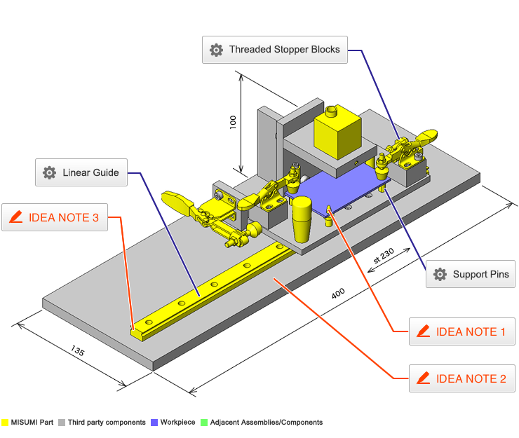
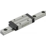
Linear Guide
| Product name | Miniature Linear Guides - Long Blocks |
| Part number | SSELB16-350 |
| Features | Compliant with the industry standard specifications. Higher load ratings and allowable moments than standard blocks. |
* Orange colored cells in the table below indicate the part numbers used in this example.
Selection criteria
Stable linear motion is required often.
Back to page top.
Available sizes
■Miniature Linear Guides - Long Blocks
| Material | Hardness |
| Stainless Steel (440C Stainless Steel) | 56HRC- |
| Carbon steel (SCM, etc. alloy) | 58HRC- |
■Sizes and Dimensions.
| Number of Blocks | Block Width | Block Length | Overall Height | Rail Length |
| 1 | 12 | 21 | 6 | 40-100 |
| 17 | 32 | 8 | 40-130 |
| 20 | 40 | 10 | 65-275 |
| 27 | 45.8 | 13 | 70-470 |
| 32 | 58.3 | 16 | 110-670 |
| 40 | 67.7 | 20 | 160-700 |
| 2 | 12 | 21×2pcs. | 6 | 70-100 |
| 17 | 32×2pcs. | 8 | 85-130 |
| 20 | 40×2pcs. | 10 | 95-275 |
| 27 | 45.8×2pcs. | 13 | 120-470 |
| 32 | 58.3×2pcs. | 16 | 150-670 |
| 40 | 67.7×2pcs. | 20 | 220-700 |
* Please see the product pages for details of selectable sizes.
Back to page top.
Selection Steps
■Miniature linear guide selection steps.
- Determination on Operating Conditions.
- (Moving mass, feed rate, motion pattern, life).
↓
- Temporary selection of linear guide specifications.
- (Block type, overall height, rail length are temporarily selected according to the conditions of use.).
↓
- Basic safety check.
-
- Allowable Load.
- Operating Life.
- Preload.
Back to page top.
Accuracy Info
■Preload and Accuracy Standards (Long Blocks / Light Preload / High Grade).
(μm)
| Radial Clearance | -3~0 |
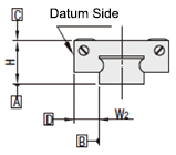
| H Dimension Tolerance | ±20 |
| Pair variation of H | 15 |
| Tolerance of dims. W2 | ±25 |
| Pair variation of W2 | 20 |
(μm)
| Rail Length (mm) |
| -80 | 81-200 | 201-250 | 251-400 | 401-500 | 501-630 | 631-700 |
| Running Parallelism | 3 | 7 | 9 | 11 | 12 | 13.5 | 14 |
Back to page top
Performance info.
Load Rating of Linear Guides (Standard block / Light Preload / High Grade).
| Overall Height | Basic Load Rating | Allowable Static Moment |
| C (Dynamic) kN | C0 (Static) kN | MAN+m | MBN+m | McN+m |
| 6 | 0.3 | 0.6 | 0.8 | 0.8 | 1.5 |
| 8 | 0.9 | 1.5 | 4.1 | 4.1 | 5.2 |
| 10 | 1.5 | 2.5 | 5.1 | 5.1 | 10.2 |
| 13 | 2.2 | 3.3 | 8.8 | 9.5 | 16.1 |
| 16 | 3.6 | 5.4 | 21.6 | 23.4 | 39.6 |
| 20 | 5.2 | 8.5 | 48.4 | 48.4 | 86.4 |

Back to page top.
Technical Calculations
Operating Life Calculation for Linear Guides.
- Operating Life.
- When the linear guide is loaded in linear reciprocating motion, scaly damages called flaking appear due to material fatigue as the stress works on the rolling elements (steel balls) and the rolling contact surfaces (rails) constantly.Total travel distance until the first flaking occurs is called Life of Linear Guides.
- Rated life.
- Rated life is the total travel distance that 90% of linear guides of the same type can reach, under the same conditions, with no occurrence of flaking damage.Rated life can be calculated with the basic dynamic load rating and the actual load applied on the linear guides, as shown below.
-

- Load must be calculated before actually using linear guides.To obtain loads during linear reciprocating motion, it is necessary to fully consider vibrations and impacts during motion as well as distribution condition of the load applied to linear guides. So, it is not easy to calculation the loads.In addition, the factors as operating temperature also significantly affect the life. Considering these conditions, the above-mentioned calculation formula will be as follows.
-

- L: Rated Life (Km).
- fH: Hardness Factor (See Fig.1).
- fT: Temperature Factor (See Fig.2).
- fC: Contact Factor (See Table-1).
- fW: Load Factor (See Table-2).
- C: Basic Dynamic Load Rating (N).
- P: Applied Load (N).
- Hardness factor (fH).
-
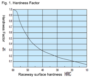
For Linear Guide applications, sufficient hardness is required for ball contact shafts.Inappropriate hardness causes less allowable load, resulting in shorter life.
Please correct the rated life with the hardness factor.
- Temperature factor (fT).
-
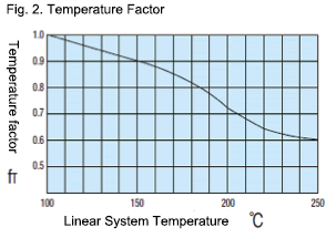
When the temperature of linear guides exceeds 100 C, the hardness of guides and shafts will be reduced, and the allowable loads will also be reduced compared to being used at room temperature, causing a reduction of life.Please correct the rated life according to the temperature factors.
* Please use Linear Guides at within the heat resistance temperature ranges shown on product pages.
- Contact factor (fC).
-
Table-1. Contact factor.
Number of blocks per rail Contact factor fC.
| 1 | 1.00 |
| 2 | 0.81 |
| 3 | 0.72 |
| 4 | 0.66 |
| 5 | 0.61 |
For actual applications, more than 2 blocks are generally used per shaft.In this case, the load applied to each block varies depending on machining precision and is not uniformly distributed.As a result, per-block allowable load varies depending on the number of blocks per rail.Please compensate rated life with Contact Factors on Table - 1.
- Load Factor (fW).
-
Table-2. Load factor.
| Conditions of Use | fw |
| No shocks/vibrations, low speed: 15m/min. or less | 1.0-1.5 |
| No significant shocks/vibrations, medium speed: 60m/min. or less | 1.5-20 |
| With shocks/vibrations, high speed: 60m/min. or more | 2.0-3.5 |
To calculate load applied to the Linear Guides, in addition to object weight, it requires inertia force attributed to motion velocity or moment loads.However, it is difficult to calculation the load accurately due to potential vibrations and shocks caused by other element than repeated start-stop motions during reciprocating motion.Thus, table-2 load factor helps simplify the life calculation.
- Applied Load P Calculation Method.
- When load is applied to the a block, convert moment load into applied load by the following formula.
-
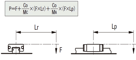
- P: Applied Load (N).
- F: Downward load (N).
- C0: Static load rating (N).
- MA: Allowable static moment - Pitching direction (N・m).
- MC: Allowable static moment - Rolling direction (N・m).
- Lp: Load point distance (m) in pitching direction.
- Lr: Load point distance (m) in rolling direction.
Back to page top
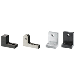
Threaded Stopper Blocks
| Product name | Locating Screw Stopper Blocks L-Shaped Bottom Mounting Type Fine Thread |
| Part number | AJLTTS4-20 |
* Orange colored cells in the table below indicate the part numbers used in this example.
Selection criteria
The slim body is suitable for the parts layout.
Back to page top.
Available sizes
■Locating Screw Stopper Blocks L-Shaped Bottom Mounting Type Fine Thread
| Material | Surface Treatment | Adjusting Screw Type |
| Coarse Thread | Fine Thread |
| 1045 Carbon Steel | Black Oxide | ○ | ○ |
| Electroless Nickel Plating | ○ | ○ |
| 304 Stainless Steel | ? | ○ | ? |
■Sizes and Dimensions.
| Adjustment Screw | Overall Height | Overall Width | Overall Length | Plate Thickness | Mounting Screw |
| Diameter | Pitch | Center Height |
| Coarse Thread | Fine Thread |
| M3 | 0.5 | 0.35 | 15・20 | Center Height +4 | 9 | 25 | 6 | M4 |
| M4 | 0.7 | 0.5 |
| M5 | 0.8 | 0.5 | 15 | Center Height +6 | 12 | 32 | 8 | M5 |
| M6 | 1 | 0.75 |
| M8 | 1.25 | 0.75 | 25・30・35 | Center Height +10 | 22 | 44 | 10 | M6 |
| M10 | 1.5 | 1 |
| M12 | 1.75 | 1 |
| M16 | 2 | 1.5 | 35・40 | Center Height +15 | 30 | 65 | 15 | M8 |
| M20 | 2.5 | 1.5 |
Back to page top.
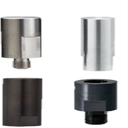
Support Pins
| Product name | Support Pins- Flat, Round, Flat, Threaded |
| Part number | STPASU6-L11.5 |
| Features | This can be used for horizontal / vertical positioning on high locations. |
* Orange colored cells in the table below indicate the part numbers used in this example.
Selection criteria
Standards to secure the required height accuracy.
Back to page top
Available sizes
■Support Pins- Flat, Round, Flat, Threaded
| Material | Surface Treatment | Hardness |
| 1045 Carbon Steel | Black Oxide | ? |
| Hard Chrome Plating | - |
| Black Oxide | Treated Hardness 45 - 50 HRC |
| Hard Chrome Plating | Heat treated hardness 45?50HRC |
| 304 Stainless Steel | - | - |
| 440C Stainless Steel | ? | Heat treated hardness 50?55HRC |
■Sizes and Dimensions.
| Pin Dia. | Pin section length | Thread | Wrench flats |
| 0.01 mm Increments | DIA. (Coarse) | Length |
| φ6 | 10.00?50.00 | M3 | 4.5 | 5 |
| φ8 | M5 | 7.5 | 7 |
| φ10 | 20.00?80.00 | 8 |
| φ12 | 10 |
| φ15 | M8 | 12 | 13 |
| φ20 | 17 |
Back to page top
Accuracy Info
■Accuracy of Support Pins Flat Type.
Pin DIA. Tolerance: ±0.1.
Pin Section Length Tolerance: +0.05/0.
Back to page top.
IDEA NOTE Workpiece setting repeatability
Mechanism in which a workpiece is positioned by a locating pin and retained by a toggle clamp.
IDEA NOTE Improvement of workpiece setting workability
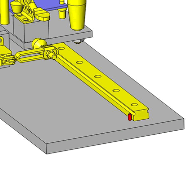
As the work piece inspecting position can be moved using the linear guide, it is possible to perform inspection in multiple positions.
IDEA NOTE The linear guide rail presser pin prevents the linear guide block from coming off.
As the work piece is positioned the linear guide could run off the track, to prevent this a rail presser pin also serves as a block retainer.


