(!)Due to Microsoft's end of support for Internet Explorer 11 on 15/06/2022, this site does not support the recommended environment.

- inCAD Library Home
- > No.000126 Simplified Welding Mechanism
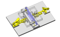
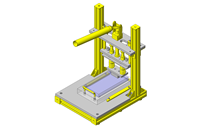
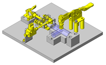
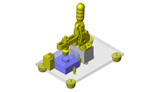
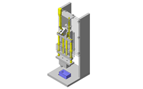
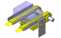
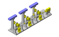
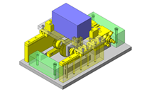
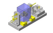
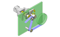
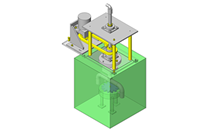
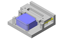
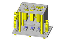
No.000126 Simplified Welding Mechanism
Welding mechanism utilizing a cylinder
Relevant category


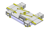
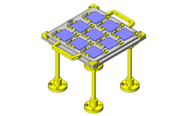
Welded Steel Stands
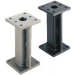
| Product name | Welded Steel Stands- No Hole Type |
|---|---|
| Part number | YSFT100-B100-H300-G80-F80 |
Selection criteria
To secure the rigidity of the unit
Available sizes
■Welded Steel Stands- No Hole Type
| Material | Surface Treatment |
|---|---|
| 1018 Carbon Steel | − |
| Black Oxide | |
| Electroless Nickel Plating | |
| 304 Stainless Steel | − |
■Sizes and Dimensions
| Plate (Top Plane, Bottom Plane) | Overall Height (50mm increments) | Screw Dia. (Coarse) | Through Hole Dia. | ||||
|---|---|---|---|---|---|---|---|
| Length | Length Direction Hole pitch (1mm Increment) | Width | Width Direction Hole Pitch (1mm Increment) | Plate Thickness | |||
| 100 | 30〜80 | 100 | 70〜80 | 10 | 100~300 | M10 | φ11 |
| 30〜100 | 120 | ||||||
| 30〜130 | 150 | ||||||
| 125 | 30〜100 | 120 | 95〜100 | ||||
| 150 | 35〜120 | 150 | 95〜120 | 14 | M12 | φ14 | |
| 200 | 35〜170 | 200 | 120〜170 | ||||
Accuracy Info
■Accuracy of Welded Steel Stands Type (Hole Position Specifying Type)
Overall Height Tolerance: ±0.1mm
Parallelism of Plates (Top Plane, Bottom Plane) 0.05/100mm

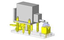
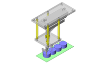
Plate Heaters

| Product name | Plate Heaters |
|---|---|
| Part number | MPHKH-100-100-V100-W250 |
Selection criteria
Suitable for heating the flat shape workpieces.
Available sizes
■Plate Heaters
| No. | Name | Material |
|---|---|---|
| ① | Cover of the Heater | 430 Stainless Steel |
| ② | Mica for Insulation | Synthetic Mica |
| ③ | Nickel-chrome Wire | Nickel Chrome Ribbon Wire |
| ④ | Lead Wire | Nickel Copper Glass Fiber Coated Wire |
| ⑤ | Tube | Glass Fiber |
■Specifications
| Plate External Shape | Voltage (Single phase) V | Electric Power (W) | Electrical Power Density (W/cm²) | Lead Wire Length | ||
|---|---|---|---|---|---|---|
| Length | Width | Plate Thickness | ||||
| 100 | 100 | 4 | 100・200 | 250 | 2.5 | 1000 |
| 150 | 150 | 500 | 2.2 | |||
| 200 | 50 | 200 | 2.0 | |||
| 100 | 400 | |||||
| 250 | 50 | 250 | ||||
| 300 | 50 | 350 | 2.3 | |||
Accuracy Info
■Plate Heaters (with Through Holes), Tolerance of Plate External Shape
Length Tolerance: 0/-2mm
Width Tolerance: 0/-2mm
Plate Thickness Tolerance: ±1mm

Heat Insulating Board
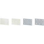
| Product name | Heat Insulating Plates - Standard / Heat Resistant Grade |
|---|---|
| Part number | HIPA4H-100-100-10-F80-G80-N6 |
| Features | Low thermal conductivity, lightweight, excellent heat retention and temperature insulation |
Selection criteria
It does not conduct heat to other components.
Available sizes
■Heat Insulating Plates - Standard / Heat Resistant Grade
| Grade | Color | Operating Ambient Temperature |
|---|---|---|
| Standard | White | Room temperature - 220°C |
| Heat Resistance | Gray | Room temperature - 500°C |
■Sizes
| External Shape | Number of Holes | Hole Type | ||
|---|---|---|---|---|
| Plate Thickness | Length | Width | ||
| (Configure in 1mm increments) | ||||
| 3 | 20~800 | 20~600 | 2・4・6 | Through Hole, Counter Bore, Threaded Inserts |
| 5 | ||||
| 10 | ||||
| 15 | ||||
* Selectable Machined Hole Specification will vary with the plate thickness.
Please see the product pages for details.


-
 Terms of use of CAD data and simplified drawing data
- These terms and conditions (hereinafter referred to as “the Terms") set forth the conditions for downloading CAD data and simplified drawing data posted on https://my.misumi-ec.com/ (hereinafter referred to as the "Website") operated by MISUMI MALAYSIA SDN. BHD. (hereinafter referred to as "MISUMI"). By downloading CAD data and simplified drawing data posted on the Website (hereafter referred to as “Data”), customers are deemed to have agreed to these Terms.
- 1. Purpose of Use
-
MISUMI offers the following:
1)CAD data found on the Website (3D CAD data, 3D Intermediate data and 2D CAD data) for the purpose of informing customers of the characteristics of the products offered by MISUMI or a manufacturer affiliated with MISUMI for use in their designs.
2)Simplified drawing data (in PDF format) for the purpose of checking the specifications of products. - 2. Characteristics of Data
- There may be a discrepancy in certain characteristics of products (for example: tolerance, surface roughness, chamfer, etc.) between the Data and the actual product. Furthermore, for the purpose of reducing the file size of the Data, some information such as oil groove shapes, threads, or spring shapes, may be removed from the Data.
- 3. Disclaimer
- MISUMI carefully creates the Data but makes no warranty as to the accuracy of the Data. MISUMI may at any time, and with no prior notice to customers, revise or delete Data. MISUMI assumes no responsibility for any damage or loss resulting from any revision or deletion of the Data, or any errors in said data. Customers are solely responsible for all aspects of their own designs, including those made using MISUMI’s CAD data. MISUMI may provide customers with design example data on the Website, but the quality, accuracy, functionality, safety, reliability, etc., of such data are not guaranteed. MISUMI may, at any time, and in its sole discretion, request that the customer cease its use of or destroy the Data in its possession. MISUMI may request the customer provide MISUMI documentation of such destruction.
- 4.Prohibited Acts
-
Customers or users of the Data, are prohibited from the following acts regarding the Data, in whole or in part:
(1)Requesting quotations or placing orders for products with third parties other than those authorized by MISUMI or its affiliates;
(2)Receiving quotations or orders for products from third parties by providing the Data to a third party or using the Data in their own business;
(3)Displaying links to the Website related to the Data on their own websites, etc., without MISUMI's consent;
(4)Using or reproducing the Data beyond the scope of the above-stated Purpose of Use;
(5)Modifying, altering, tampering with, translating, or adapting the Data;
(6)Selling, transferring, lending, sublicensing, or providing the Data to third parties in any way without MISUMI’s consent;
(7)Altering the content, reverse engineering, decompiling, disassembling, or analyzing the Data;
(8)Publicly disclosing or exhibiting the Data without MISUMI's consent;
(9)Using the Data for the purpose of providing products and services identical or similar to those of MISUMI;
(10)Performing acts that interfere with the proper functioning of this Website, such as acquiring Data in bulk. - 5. Copyright
-
All title and copyright in and to any information contained in the Data are owned by MISUMI or the relevant manufacturer affiliated with MISUMI and are protected by applicable copyright laws and international treaties. By downloading Data, the customer acquires no ownership rights of any kind in the intellectual property contained within. Without prior approval from MISUMI, no part of the Data may be utilized (reproduced, modified, reverse-engineered, uploaded, presented, sent, distributed, licensed, sold, or published) for any purpose other than that mentioned above.
In the event Data is found to have been to be used for any purpose other than that mentioned above or against any applicable laws, MISUMI may pursue any legal remedy available to it, which may result in forbidding the offending user from using the Data or accessing the Website. - 6. Third-Party Data
- MISUMI offers some Data provided by third parties. Such Data may be subject to separate terms and conditions, in addition to these terms. MISUMI makes no guarantee or warranty regarding Data from third parties.
- 7. Export Control
- Customers shall comply with all applicable laws and regulations regarding the export of the Data.
- 8. Amendments to the Terms
- MISUMI may, at any time, and in its sole discretion, modify these terms and conditions; any such modification will be effective immediately.
- 9. Severability
- If any term or provision of these Terms is invalid, illegal, or unenforceable in any jurisdiction, such invalidity, illegality, or unenforceability shall not affect any other term or provision of these Terms or invalidate or render unenforceable such term or provision in any other jurisdiction.
- 10.Miscellaneous
- These Terms and any disputes arising in connection therewith shall be exclusively governed by and construed in accordance with the laws of Malaysia, without regard to its conflicts of law principles. The authorized courts in Malaysia shall have exclusive jurisdiction to adjudicate any dispute arising in connection with these Terms.
- Revised: 16th November, 2025
CAD Download (Unit Assembly)
CAD Download: File Format
CAD Data Limitations
-
Assembly data shows the assembly drawings in the concept design phase. The sole purpose of the data is to explain the structure and functionality of the assembly and is not considered nor to be used as a final design.
You will need to edit the Data so that it meets your specific design conditions. -
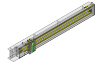
Unit assembly Data consists of some sub-assemblies.
It is configured so that each sub-assembly unit can be used as it is or edited. - The Data for fabricated parts is based on easy-to-edit dimensions and shapes in sketches and histories.
- The Data including the third-part components are made by the Company.
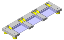
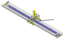
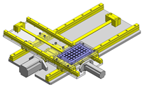
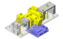
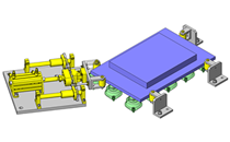
* The part in the frame is a sub-assembly unit.
-

- * Unit assembly Data consists of some sub-assemblies.
It is configured so that each sub-assembly unit can be used as it is or edited.
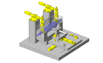
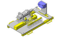
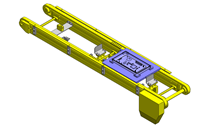
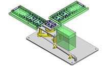
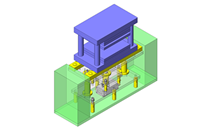
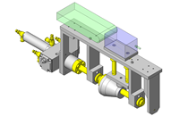
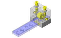
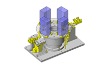
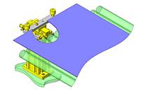
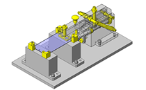
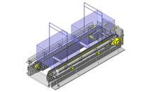
Application Overview
Purpose
- Device capable of welding small size workpieces.
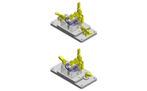
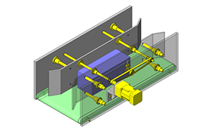
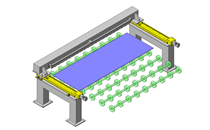
- Operation steps:
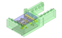
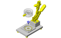
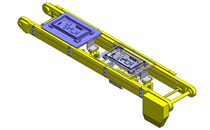
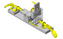
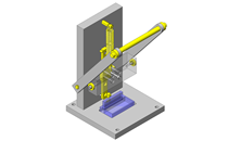
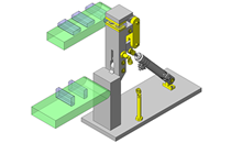
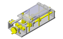
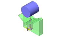
(1) Horizontal cylinder with a guide advances to clamp a workpiece.
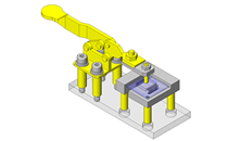
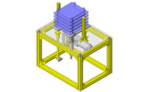
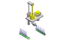
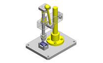
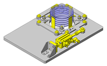
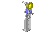
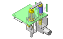
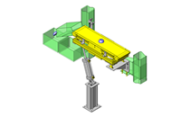
(2) Vertical cylinder with plate heaters descends.
(3) The plate heater welds workpieces 1 and 2.
(4) Vertical cylinder controlled by timer returns to start position.
(5) Clamp cylinder retracts.
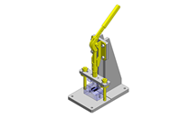
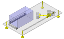
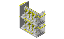
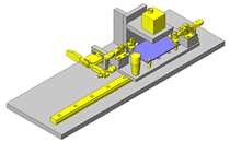
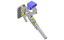
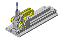
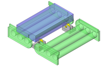
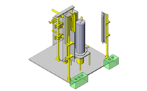
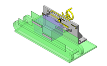
Points for use
- An automatic mechanism in which the cylinder raises and lowers the heater and retains the workpiece during welding operation.
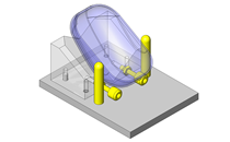
- Workpieces are manually inserted and removed by the worker using a dedicated tool (vacuum pad).
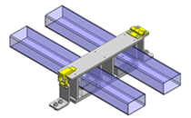
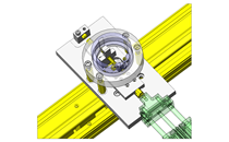
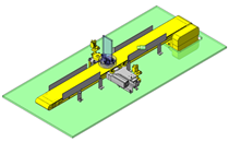
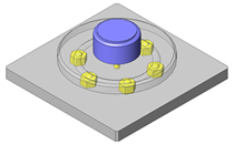
Target workpiece
- Resin case outer dimensions: W40xD40xH6
- Film sheet outer dimensions: W36xD36xt0.5
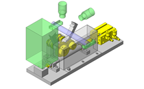
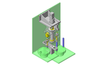
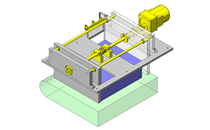
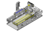
Design Specifications
Operating Conditions or Design Requirements
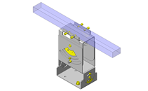
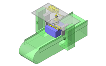
- Outer dimensions: W350xD250xH325
- Heat welding cylinder stroke: 74mm
- Workpiece retention cylinder stroke: 17mm
- Thrust of heat welding cylinder: 235.5N (from manufacturer's catalog)
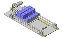
Required Performance
- Heater power: 142W
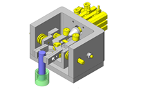
Selection Criteria for Main Components
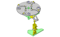
- Plate heater
- Select the size based on heat requirements to weld workpieces and the dimensions of the workpieces.
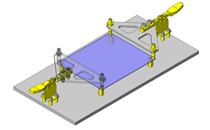
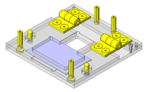
- Cylinder with a guide
- A cylinder with a guide that can withstand the allowable lateral load of 19N is selected.
Design Evaluation
Verification of main components
- Verify that the selected heater calorific value and cylinder allowable lateral load are sufficient for this application.
- Heat quantity required for the heater
- Mass of heated workpiece: 0.725kg (304 Stainless Steel)
- Specific heat of heated workpiece: 0.11kcal/kg°C
- Temperature rise: 230°C (heated until the temperature of the heated workpiece reaches 250°C)
- Heating time: 0.5 h (idling)
- Heating time: approx. 5sec (workpiece)
- The workpiece heating time should be determined through trial and error because it depends on the size, thickness, and material of the workpiece.
- Efficiency: 0.3
- Calculation formula: power for heater (kw) = mass of heated workpiece (kg) x specific heat of heated workpiece (kcal/kg°C) x temperature rise (°C)/(860 x heating time (h) x efficiency (η)) = 0.142 kW = 142W
- Cylinder with guide
- Weight of parts in moving unit: (0.0975kg + 0.0368kg) x 9.8 = 1.302N
Calculated value is below the allowable lateral load of the selected cylinder.
- Weight of parts in moving unit: (0.0975kg + 0.0368kg) x 9.8 = 1.302N
Other Design Consideration
- Welding time is controlled by a timer.
- A heat insulation material is used to prevent the heat of the heater from being transmitted to the upper and lower moving parts.
Explore Similar Application Examples

-
-

-
-
-
-
-
-
-

-
-

-
Relevant category
-
-
-
-
-
-
-
-

-
-
-

-

-

-
-

-
-
-
-

-
-
-
-

-
-
-
-

-

-
-
-
-
-

-
-

-

-
-
-
-
-
-

-
-

-

-
-
-
-
-

-
-
-
-

-
-

-
-

-

-
-

-
Relevant category
-

-
-
-
-

-
-
-
-
-

-

-
-
-

-

-
-
-

-
-
-
-

-
-
-
-
-
-

-
-
-

-
-

-

-
-
-
-
-

-
-
-

-
-

-
-

-
-

-
-

-

-
-

-
-

-
-

-
-
-

-

-
-

-

- Credit Card
- Bank Transfer
Social Media
MISUMI Contact
Copyright © MISUMI Corporation All Rights Reserved.