Tensioner Units
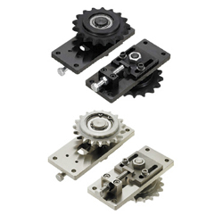
| Product name | Tensioner Units |
| Part number | TNSR10-Y28-F10 |
| Features | Tensioner unit easy to assemble. Can be used by chain or belt drive. |
* Orange colored cells in the table below indicate the part numbers used in this example.
Selection criteria
Utilizing a commercially available part diminishes design time.
Back to page top
Available sizes
■Tensioner Units
| Material | Surface Treatment |
| Fixing Plate | Tension Pin | Slide Plate | Tension Block |
| 1018 Carbon Steel-D | 1045 Carbon Steel | 1045 Carbon Steel
(precision casting) | 1018 Carbon Steel-D | Black Oxide |
| Electroless Nickel Plating |
■Sizes and Dimensions
Tension Pin
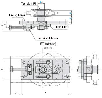
Shaft Dia. | 1mm Increments | Stroke | A | B | T | J | Z |
| Y | F |
| 10 | 10~50 | 8~50 | 25 | 120 | 50 | 6 | 24 | 21 |
| 12 |
| 15 | 12~60 | 10~50 | 25 | 125 | 55 | 9 | 31 | 29 |
| 17 | 30 | 140 | 60 | 30 |
| 20 |
Back to page top
Idlers with Teeth
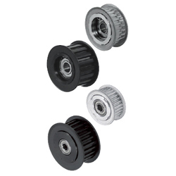
| Product name | Flanged Idlers with Teeth - P2M / P3M / P5M / P8M / 2GT / 3GT / 5GT / 8YU |
| Part number | AGTF24GT5120 |
| Features | Can be used as the tension adjuster for timing belts or as the pulley on the driven side. |
* Orange colored cells in the table below indicate the part numbers used in this example.
Selection criteria
Select commercially available item because it simplifies the design.
Back to page top
Available sizes
■Flanged Idlers with Teeth - P2M / P3M / P5M / P8M / 2GT / 3GT / 5GT / 8YU
| Type | Material | Surface Treatment |
| Center Bearing | Both Sides Bearing | Main Body | Flange | Bearing |
| ○ | ○ | 2017 Aluminum Alloy | 5052 Aluminum Alloy | Steel | Clear Anodize |
| - | - | Hard Clear Anodize |
| ○ | ○ | 1045 Carbon Steel | Low Carbon Steel | Black Oxide |
■Sizes and Dimensions
| Number of Teeth | Applicable Belt | Shaft Dia. | Standard Circle Dia. | O.D. | Tooth Width |
| 40 | GT2060 | 6 | 25.46 | 24.96 | 30 |
| GT2090 | 6 |
| 30 | GT3060 | 6 | 28.65 | 27.89 | 32 |
| GT3090 | 6 |
| 20 | GT5090 | 8 | 31.83 | 30.69 | 35 |
| GT5120 | 8 |
| 24 | GT5090 | 10 | 38.20 | 37.06 | 42 |
| GT5120 | 10 |
| 28 | GT5090 | 10 | 44.56 | 43.42 | 48 |
| GT5120 | 10 |
| 30 | GT5090 | 12 | 47.75 | 46.61 | 51 |
| GT5120 | 12 |
| 20 | YU8150 | 20 | 50.93 | 49.56 | 62 |
| YU8200 | 20 |
| 30 | YU8150 | 25 | 76.39 | 75.02 | 85 |
| YU8200 | 25 |
| YU8250 | 25 |
Back to page top
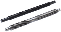
Lead screw
* Orange colored cells in the table below indicate the part numbers used in this example.
Selection criteria
Select a Lead screw with both left and right hand threading.
Back to page top
Available sizes
■Lead Screws - Both Ends Stepped
| Material | Surface Treatment | Compatible Lead Screw Nut |
| Type | Material |
| 1045 Carbon Steel | ? | Right / Left-hand Thread | Brass |
| Black Oxide |
| Low Temp. Black Chrome Plating |
| 303 Stainless Steel | ? |
■Sizes and Dimensions
| Screw Shaft Nominal | Pitch | Overall Length
1mm Increments |
| 14 | 3 | 80?1000 |
| 16 | 100?1200 |
| 18 | 4 | 150?1200 |
| 20 |
| 22 | 5 |
| 25 |
| 28 |
| 32 | 6 | 200?1200 |
Back to page top
Accuracy Info
■Lead Screw: Screw Shaft Runout Tolerance (Max.)
(mm)
| Shaft Dia. | Screw Shaft Length |
| -125 | 126
-200 | 201
-315 | 316
-400 | 401
-500 | 501
-630 | 631
-800 | 801
-1000 | 1001-
1250 | 1251-
1600 | 1601-
2000 |
| φ8 | 0.1 | 0.14 | 0.21 | 0.27 | 0.35 | - | - | - | - | - | - |
| φ10-12 | 0.09 | 0.12 | 0.16 | 0.21 | 0.27 | 0.35 | 0.46 | 0.58 | - | - | - |
| φ14 | 0.09 | 0.11 | 0.13 | 0.16 | 0.2 | 0.25 | 0.32 | 0.42 | - | - | - |
| φ16 | 0.09 | 0.11 | 0.13 | 0.16 | 0.2 | 0.25 | 0.32 | 0.42 | 0.55 | 0.73 | 1 |
| φ18-20 | - | 0.11 | 0.13 | 0.16 | 0.2 | 0.25 | 0.32 | 0.42 | 0.55 | 0.73 | 1 |
| φ22-32 | - | 0.09 | 0.11 | 0.13 | 0.16 | 0.19 | 0.23 | 0.3 | 0.38 | 0.5 | 0.69 |
| φ36-50 | - | 0.11 | 0.11 | 0.11 | 0.13 | 0.15 | 0.17 | 0.22 | 0.27 | 0.34 | 0.46 |
■Lead Screw Accuracy Standards
| Item | Content |
| Allowable Dimension and Tolerance | JISB0217 0218 |
| Screw Accuracy | 7e Class |
| Nut Accuracy | 7H Class |
| Single Pitch Error | ±0.02 |
| Accumulated Pitch Error | ±0.15/300mm |
| Length Tolerance | JISB0405 (medium class) |
| Screw Shaft End DIA. Tolerance | h7 |
Back to page top
Technical calculations
■Lead Screw and Lead Screw Nut Selection Steps
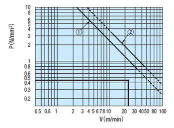
Calculate Contact Pressure P and Sliding Velocity V based on conditions of use to check that no abnormal wear will occur.
Plot the calculated P and V values against the PV value graph and confirm the intersection.
If the intersection falls inside of line (1) and (2), it is determined that abnormal wear would not occur
Determine Conditions of Use
↓
Lead Screw and Lead Screw Nut Temporary Selection
↓
(1) Contact surface pressure P, (2) Sliding speed V calculations
Verify that the value is within (1) and (2) of the PV value graph
↓
Calculate Screw Efficiency η and Load Torque T
(axial load, rotational speed)
(lead screw and lead screw nut material)
↑
(If not good)
- (1) Steel (lubrication) - Brass
- (2) Steel (non-lubrication) - Plastic
(1) Contact Surface Pressure P (N/mm²)
- Fs: Shaft Axial Load (N)
- F0: Allowable Dynamic Thrust (N) -> Nuts for Lead Screw Specifications
Thrust when contact surface pressure of the lead screw and nut becomes 9.8 (N/mm²) - α: 9.8 (brass) 0.98 (plastic)
(2) Sliding Speed V (m/min)
- d2: Screw Shaft Effective DIA. → From Lead Screw Specifications Table
- d: Screw Shaft Lead Angle (deg.) -> Lead Screw Specifications
- n: Screw Shaft Rotation per Minute (min-1)
(3) Screw Efficiency η
- μ: Dynamic Friction Coefficient
- d: Screw Shaft Lead Angle (deg.)
| Thread Shaft | Nuts for Lead Screws | Dynamic Friction Coefficient μ |
| Steel (lubrication) | Brass | 0.21 |
| Steel (non-lubrication) | Polyacetal/
PPS Resin with Sliding Property | 0.13 |
(4) Load Torque (N・cm)
- Fs: Shaft Axial Load
- η: Screw Efficiency
- R: Lead (cm)
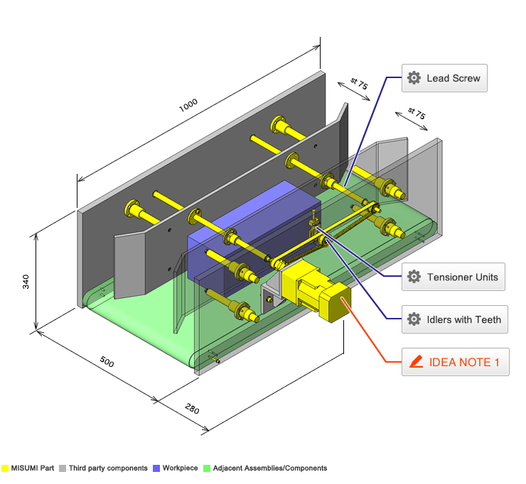
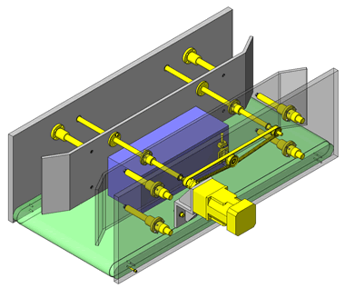
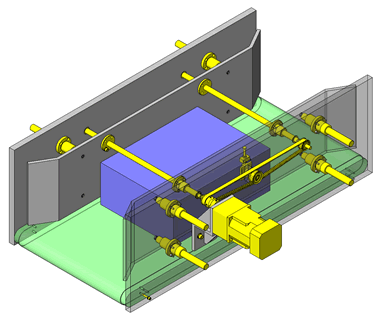
IDEA NOTE Continuous changeover of the workpiece guides
The guides are moved to any width by rotating the left and right screws with a motor.


