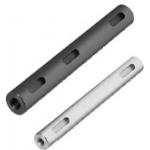
Rotary Shaft
| Product name | Rotary Shafts - Both Ends Tapped with Key Grooves |
| Part number | PSFHKRW15-76-M5-N5-KA0-A25-KB56-B20 |
| Features | Tolerance Options: g6 (ground), h7 (ground) and h9 polished |
* Orange colored cells in the table below indicate the part numbers used in this example.
Selection criteria
Economical
Back to page top
Available sizes
■Rotary Shaft (Both Ends Tapped, with Keyway Type)
| O.D. tolerance | Material | Surface Treatment |
|
| h9 (Cold-drawn) | 1045 Carbon Steel | Black Oxide |
| Electroless Nickel Plating |
| 304 Stainless Steel | - |
| h7 (Ground) | 1045 Carbon Steel | Black Oxide |
| Electroless Nickel Plating |
| 304 Stainless Steel | - |
| g6 (Ground) | 1045 Carbon Steel | Black Oxide |
| Electroless Nickel Plating |
| 304 Stainless Steel | - |
■Sizes
| O.D. Tolerance | O.D. | Length
(Configure in 1mm increments) |
| h9 | φ6 | 20.0~300.0 |
| φ8 | 20.0~400.0 |
| φ10 | 20.0~500.0 |
| φ12 | 30.0~600.0 |
| φ15 | 30.0~700.0 |
| φ20 | 40.0~800.0 |
| φ25 | 50.0~800.0 |
| φ30 | 60.0~800.0 |
| φ35 | 70.0~800.0 |
| h7 | φ6 | 20.0~300.0 |
| φ8 | 20.0~400.0 |
| φ10 | 20.0~500.0 |
| φ12 | 30.0~600.0 |
| φ15 | 30.0~700.0 |
| φ20 | 40.0~800.0 |
| φ25 | 50.0~800.0 |
| φ30 | 60.0~800.0 |
| φ35 | 70.0~800.0 |
| φ40 | 80.0~800.0 |
| φ50 | 100.0~800.0 |
| g6 | φ6 | 20.0~300.0 |
| φ8 | 20.0~400.0 |
| φ10 | 20.0~500.0 |
| φ12 | 30.0~600.0 |
| φ13 | 30.0~600.0 |
| φ15 | 30.0~700.0 |
| φ16 | 30.0~800.0 |
| φ17 | 40.0~800.0 |
| φ18 | 40.0~800.0 |
| φ20 | 40.0~800.0 |
| φ22 | 40.0~800.0 |
| φ25 | 50.0~800.0 |
| φ30 | 60.0~800.0 |
| φ35 | 70.0~800.0 |
| φ40 | 80.0~800.0 |
| φ50 | 100.0~800.0 |
■Detailed Keyway Dimensions of Rotary Shaft
| Shaft Dia. | b | t | r |
| Reference Dim. | Tolerance | Reference Dim. | Tolerance |
|
| 6 | 2 | -0.004
-0.029 | 1.2 | +0.1
0 | 0.08~
0.16 |
| 8・10 | 3 | 1.8 |
| 12 | 4 | 0
-0.03 | 2.5 |
| 13~17 | 5 | 3.0 | 0.16~
0.25 |
| 18~22 | 6 | 3.5 |
| 25・30 | 8 | 0
-0.036 | 4.0 | +0.2
0 |
| 35 | 10 | 5.0 | 0.25~
0.4 |
| 40 | 12 | 0
-0.043 | 5.0 |
| 50 | 14 | 5.5 |
Back to page top
Accuracy Info
■O.D. Tolerance Table
| O.D. | O.D. Tolerance |
| h9 | h7 | g6 |
| φ6 | 0
-0.030 | 0
-0.012 | -0.004
-0.012 |
| φ8 | 0
-0.036 | 0
-0.015 | -0.005
-0.014 |
| φ10 |
| φ12 | 0
-0.043 | 0
-0.018 | -0.006
-0.017 |
| φ13 | - | - |
| φ15 | 0
-0.043 | 0
-0.018 |
| φ16 | - | - |
| φ17 | - | - |
| φ18 | - | - |
| φ20 | 0
-0.052 | 0
-0.021 | -0.007
-0.020 |
| φ22 | - | - |
| φ25 | 0
-0.052 | 0
-0.021 |
| φ30 |
| φ35 | 0
-0.062 | 0
-0.025 | -0.009
-0.025 |
| φ40 | - |
| φ50 | - |
Back to page top
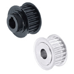
Timing Pulleys
| Product name | High Torque Timing Pulleys - 5GT |
| Part number | GPA50GT5120-A-N15 |
| Features | Circular Tooth Profile Pulleys with minimal backlash, suitable for positioning. |
* Orange colored cells in the table below indicate the part numbers used in this example.
Selection criteria
Effective for transmitting the driving force without slippage or speed changes
Back to page top
Available sizes
■Timing Pulleys (5GT Type)
| Material | Surface Treatment | Accessory
Set Screw |
| Pulley | Flange |
2017 Aluminum Alloy
(Duralumin) | 5052 Aluminum Alloy | Clear Anodize | 304 Stainless Steel |
|
| 1045 Carbon Steel | Low Carbon Steel | ― | Chromium-molybdenum steel
(Black Oxide) |
| Black Oxide |
■Sizes and Dimensions
| Number of teeth | Nominal
Width | Pulley
Shape | Shaft Bore
Specs. | Shaft Bore Specs.(Configure in 1mm increments) |
| Straight Bore | Straight Bore + Tap | New JIS Keywayed Bore + Tap | Stepped Holes - Stepped Holes
(Counterbore Holes on the Hub Side) | Both Ends Stepped Bore |
|
| Hole Dia. | Hole Dia. | Counterbore Hole Dia. | Counterbore
Depth | Hole Dia. | Counterbore Hole Dia. | Counterbore
Depth |
| No Hub | With Hub | No Hub | With Hub | No Hub | With Hub | No Hub | With Hub | No Hub | With Hub | With Hub, without Hub | No Hub | No Hub | No Hub |
| 14 | 9
12
15 | No Hub
With Hub | Straight Bore
Straight Bore
+Tap
New JIS
Keywayed Bore
+ Tap
Stepped Hole
Stepped Hole
(Counterbore Holes
on the Hub Side)
Both Ends
Stepped Bore | 6-10 | 6-8 | 6-8 | - | - | - | 6 | - | 8 | - | (When no hub)
2.0 ≤
Counterbore depth
≤ Ridge width - 2.0
(When with hub)
2.0 ≤
Counterbore depth
≤ Full length - 2.0 | 6 | 8 | 3-14
Total of
counterbore depth
≤ Width - 3
|
| 15 | 6-10 | 6-10 | 6-8 | 6-8 | 6 | 8-10 | 8 | 6-8 | 8-10 |
| 16 | 6-12 | 6-12 | 6-10 | 6 | 8 | 6-10 | 6-8 | 8-12 | 8-10 | 6-10 | 8-12 |
| 18 | 6-14 | 6-14 | 6-13 | 6-9 | 8-10 | 6-10 | 6-10 | 8-12 | 8-12 | 6-12 | 8-14 |
| 20 | 6-16 | 8-15 | 8-14 | 8-10 | 8-12 | 8 | 8-14 | 8-13 | 10-16 | 10-15 | 8-14 | 10-16 |
| 22 | 8-19 | 8-19 | 8-17 | 8-12 | 8-12 | 8 | 8-17 | 8-14 | 10-19 | 10-16 | 8-17 | 10-19 |
| 24 | 8-22 | 8-22 | 8-18 | 8-16 | 8-14 | 8-10 | 8-20 | 8-16 | 10-23 | 10-18 | 8-20 | 10-22 |
| 25 | 8-22 | 8-22 | 8-20 | 8-16 | 8-16 | 8-12 | 8-20 | 8-18 | 10-23 | 10-20 | 8-20 | 10-22 |
| 26 | 10-27 | 10-24 | 10-21 | 10-16 | 10-17 | 10-13 | 10-25 | 10-20 | 12-27 | 12-22 | 10-25 | 12-27 |
| 28 | 10-27 | 10-27 | 10-24 | 10-20 | 10-19 | 10-15 | 10-25 | 10-25 | 12-27 | 12-27 | 10-25 | 12-27 |
| 30 | 10-28 | 10-28 | 10-26 | 10-22 | 10-20 | 10-16 | 10-26 | 10-26 | 12-28 | 12-28 | 10-26 | 12-28 |
| 32 | 10-32 | 10-30 | 10-30 | 10-22 | 10-23 | 10-17 | 10-30 | 10-26 | 12-32 | 12-28 | 10-30 | 12-32 |
| 34 | 12-37 | 12-32 | 12-32 | 12-24 | 12-26 | 12-18 | 12-35 | 12-28 | 14-37 | 14-30 | 12-35 | 14-37 |
| 36 | 12-37 | 12-34 | 12-34 | 12-26 | 12-30 | 12-20 | 12-35 | 12-30 | 14-37 | 14-32 | 12-35 | 14-37 |
| 40 | 12-42 | 12-36 | 12-36 | 12-26 | 12-30 | 12-22 | 12-40 | 12-32 | 14-42 | 14-34 | 12-40 | 14-42 |
| 44 | 12-50 | 12-38 | 12-42 | 12-26 | 12-30 | 12-23 | 12-48 | 12-34 | 14-50 | 14-36 | 12-48 | 14-50 |
| 48 | 12-55 | 12-42 | 12-45 | 12-30 | 12-30 | 12-26 | 12-53 | 12-38 | 14-55 | 14-38 | 12-53 | 14-55 |
| 50 | 12-59 | 12-42 | 12-45 | 12-30 | 12-30 | 12-27 | 12-57 | 12-38 | 14-59 | 14-40 | 12-57 | 14-59 |
| 60 | 12-72 | 12-44 | 12-45 | 12-30 | 12-30 | 12-30 | 12-70 | 12-40 | 14-72 | 14-42 | 12-70 | 14-72 |
Back to page top
Selection steps
■Timing pulley selection steps
* Select the timing belt together with the timing pulley.
The automated selection tool is available
http://fawos.misumi.jp/FA_WEB/pulley_us/
- Determine Operating Conditions
- Designed power, rotational speed, rotation ratio, interim shaft distance, motion pattern, etc.
↓
- Belt selection
- Belt type/Belt width
↓
- Verify Specifications
-
- Confirmation of calculated shaft distance, etc.
- Confirmation of belt tension and load
Back to page top
Accuracy Info
■Shaft Bore Dia. of Timing Pulley
| Shaft Bore Dia. | Tolerance
(H7) |
|
| 6-10 | +0.015
0 |
| 10-18 | +0.018
0 |
| 18-30 | +0.021
0 |
| 30-50 | +0.025
0 |
| 50-80 | +0.030
0 |
Back to page top
Technical Calculations
■Timing pulley technical calculations
https://my.misumi-ec.com/pdf/tech/mech/US2010_fa_p3513_3534.pdf
Back to page top
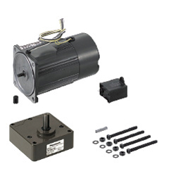
Motors with Electromagnetic Brake
| Product name | Small gearhead motor with electromagnetic brake |
| Part number | PACMB90-W40-V100 |
* Orange colored cells in the table below indicate the part numbers used in this example.
Selection criteria
Effective for the equipment requiring strong brake force or heavy load
Back to page top
Available sizes
■Motors with Electromagnetic Brake
| Type | Outer Dimensions | Output (W) | Voltage (V) | Shaft Length | Gear Head Length | Motor Length |
Single-phase
3-Phase | 60 | 6 | 100 | 32 | 26 | 75 |
| 200 |
| 70 | 15 | 100 | 30 | 80 |
| 200 |
| 80 | 25 | 100 | 30 | 85 |
| 200 |
| 90 | 40 | 100 | 37 | 105 |
| 200 |
| 60 | 100 | 38 | 50 | 120 |
| 200 |
| 90 | 100 | 130 |
| 200 |
The 3-phase motor can be used in 220 V.
Back to page top
Selection steps
■Small geared motor selection steps
- Determination of the Driving Facility
- Specify the driving facility and overall dimensions, then check required conditions for the driving facility, such as the mass and travel speed of the material to be transferred.
↓
- Calculation of rotational speed and load
- Calculate the load torque, loading moment of inertia and rotational speed at the motor driving shaft.
↓
- Confirmation of Required Specifications
- Confirm the required specifications, position accuracies, position holding, speed ranges, operating environment, and environmental resistance, etc. at the drive section and equipment.
↓
- Motor Model Selection
- Select the models most suitable for the required specifications.
↓
- Interim Selection of Motor and Gearhead
- Select motor and gearhead candidates based on calculated rotational speeds, load torque and inertia values as well as the selected motor models.
↓
- Confirmation of the Selected Motor
- Finalize the selection by confirming that all the specifications of the motor and the gearhead adequately meet the requirements.
Back to page top
Performance info.
■Small Size Geared Motor (Speed, Load)
| Type | Outer Dimensions | Output (W) | Voltage (V) | 50Hz | 60Hz |
| Rated | Starting Torque
(N·m) | Rated | Starting Torque
(N·m) |
Rotational Speed
(r/min) | Torque
(N·m) | Rotational Speed
(r/min) | Torque
(N·m) |
| Single-phase | 60 | 6 | 100 | 1300 | 0.044 | 0.056 | 1600 | 0.035 | 0.056 |
| 200 | 1300 | 0.044 | 0.056 | 1600 | 0.035 | 0.056 |
| 70 | 15 | 100 | 1300 | 0.11 | 0.10 | 1600 | 0.088 | 0.10 |
| 200 | 1300 | 0.11 | 0.10 | 1600 | 0.088 | 0.10 |
| 80 | 25 | 100 | 1300 | 0.19 | 0.20 | 1600 | 0.16 | 0.20 |
| 200 | 1300 | 0.19 | 0.20 | 1600 | 0.16 | 0.20 |
| 90 | 40 | 100 | 1300 | 0.29 | 0.32 | 1625 | 0.24 | 0.32 |
| 200 | 1300 | 0.29 | 0.32 | 1625 | 0.24 | 0.32 |
| 60 | 100 | 1275 | 0.45 | 0.57 | 1600 | 0.36 | 0.57 |
| 200 | 1275 | 0.45 | 0.57 | 1600 | 0.36 | 0.57 |
| 90 | 100 | 1225 | 0.7 | 0.68 | 1525 | 0.56 | 0.70 |
| 200 | 1225 | 0.7 | 0.68 | 1525 | 0.56 | 0.70 |
| Type | Outer Dimensions | Output (W) | Voltage (V) | 50Hz | 60Hz |
| Rated | Starting Torque
(N·m) | Rated | Starting Torque
(N·m) |
Rotational Speed
(r/min) | Torque
(N·m) | Rotational Speed
(r/min) | Torque
(N·m) |
| 3-Phase | 80 | 25 | 200 | 1350 | 0.18 | 0.54 | 1625 | 0.15 | 0.4 |
| 1375 | 0.18 | 0.66 | 1650 | 0.15 | 0.5 |
| 90 | 40 | 1350 | 0.28 | 0.72 | 1625 | 0.24 | 0.51 |
| 1375 | 0.27 | 0.88 | 1675 | 0.23 | 0.63 |
| 60 | 1350 | 0.42 | 1.0 | 1625 | 0.35 | 0.69 |
| 1375 | 0.41 | 1.2 | 1650 | 0.34 | 0.87 |
| 90 | 1350 | 0.63 | 1.6 | 1625 | 0.53 | 1.1 |
| 1400 | 0.62 | 2.0 | 1650 | 0.52 | 1.4 |
Back to page top
Technical Calculations
■Technical Calculations for Electromagnetic Brake Motors
Outline of Small Size Geared Motor
Back to page top
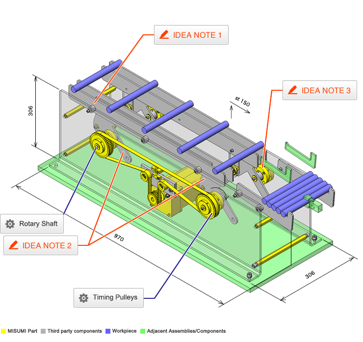
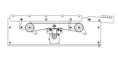
IDEA NOTE Fixed feed rate using AC motor
A fixed feed rate is achieved using an AC motor and positioning grooves for the workpieces.
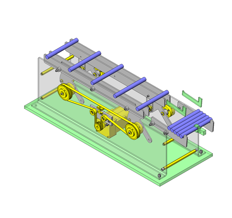
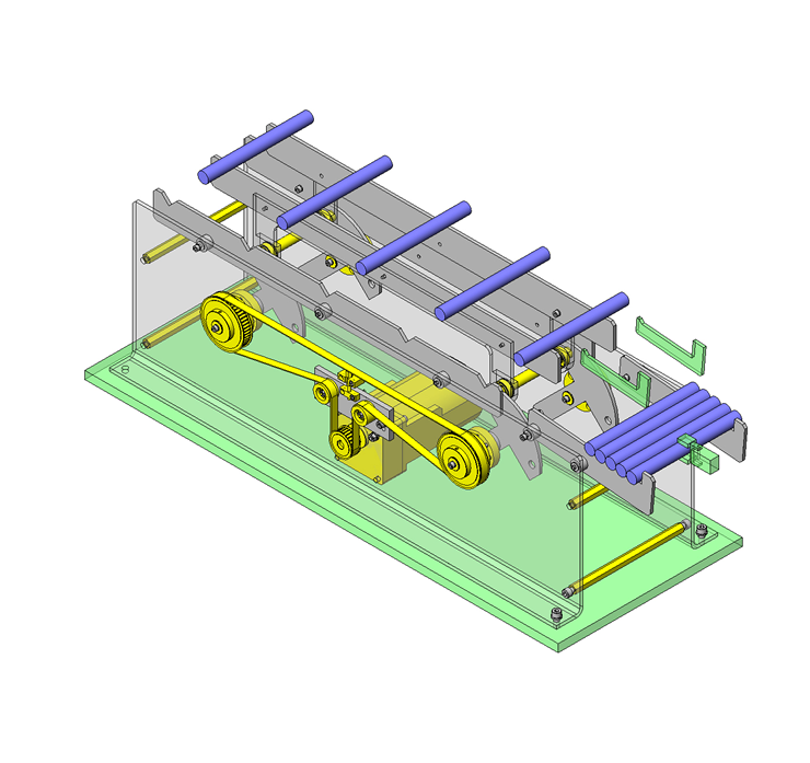
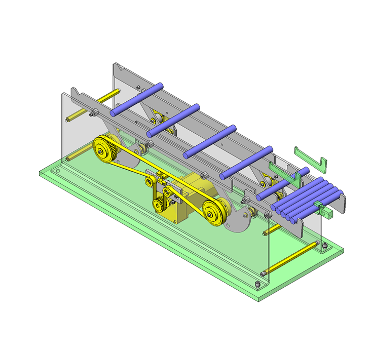
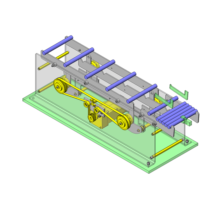
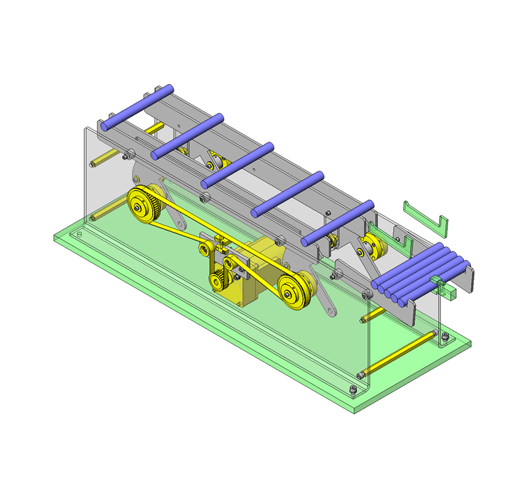
IDEA NOTE A single actuator creates lifting and carrying motions.
A parallel link structure is made by linking two eccentric shafts.
IDEA NOTE Dual single bearings
Two single bearing holders are mounted on either side of the thin plate, to serve as a double bearing.


